background image

Page

 14

User Manual

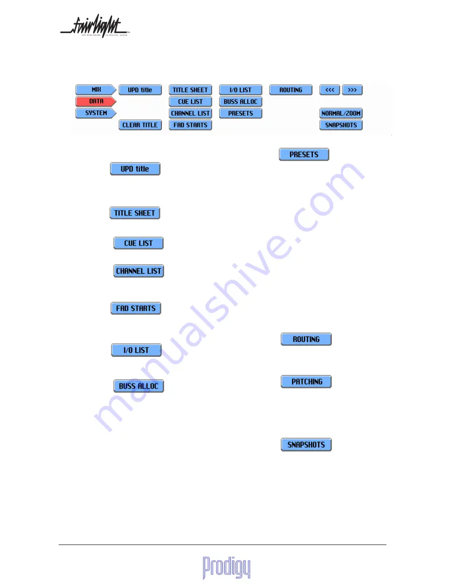
PRESETS

Allows you to see, load and save presets. A preset is

like a snapshot of all the system parameters at a given

moment, and can be used to save and restore settings

of the following:

•

Configuration of Tracks, Inputs, etc., including

names, grouping, buss allocation, routing to

busses and assignment of physical inputs and

outputs

•

Fader, EQ and Dynamics setting for each

source signal

•

Settings of outboard equipment being control-

led by the VFX system

•

Settings of all non-automated controls, such

as input trims, stereo width etc.

•

Current patching of X-Point matrix switcher

•

Current settings of Monitor Box

ROUTING

Shows you all feeds, routable busses and fader groups.

It allows you to choose which feeds are routed to which

buses, and to assign them to fader groups.

NORMAL/ZOOM

Changes the default fader screen to give an enlarged

view.

<<<        >>>

Moves the display one fader to the left or right.

SNAPSHOTS

Allows up to 64 snapshots to be made of all dynami-

cally automatable parameters.

6.4.2 The Data Menu

UPD TITLE

Saves your currently loaded title without changing its

name. Allows you to quickly get your changes safely

to disk.

TITLE SHEET

Allows you to record and store information about the

current title.

CUE LIST

A list of events that may be fired at preset timecodes.

CHANNEL LIST

A screen showing all fader channels, allowing you to

view and change their names.

FAD STARTS

If the optional GPO card is fitted, this allows the setup

of GPOs to correspond with opening and closing of

nominated faders.

I/O LIST

A list of the physical inputs and outputs, allowing

you to see the usage of these resources.

BUSS ALLOC.

Allows display and configuration of all the system

buses. This is where buses are created and assigned

physical  outputs.

Summary of Contents for Prodigy

Page 1: ...Manual by Andrew Bell Ross Caston Copyright August 2000 Mix Automation Manual Software Version 3 1 Part Number DPR1101 C Document Number 168...

Page 2: ...th respect to the system s performance or fitness for a particularpurpose In no event will Fairlight ESP Pty Ltd be liable for direct or indirect dam ages arising from any defect in the software or it...

Page 3: ...a 18 7 3 4 Using LOAD MIXDATA in the import menu 19 7 3 5 Closing a project 19 7 3 6 The UPDATE button on the Mixer 20 7 3 7 Extending Project containing embed ded Mixer Data 20 7 3 8 Removing Embedde...

Page 4: ...The Equaliser 46 9 5 4 The Auxiliary Send Panel 48 9 5 5 Dynamics 50 9 6 Joystick Operation 52 9 7 Writing Screen Macros 52 9 8 The Cue List 54 9 9 2 Presets 56 9 9 3 The Patch Library 56 9 9 VFX 57...

Page 5: ...additional SCSI card is fitted They may include fixed and removable hard disks magneto optical disks and backup tape devices 1 3 MFX Editing Console This is built into the Prodigy Mixing Surface and u...

Page 6: ...them are the outputs of the recorder editor known as Track Feeds The other 12 channels are called Live Feeds and these have sources outside the system The 12 mixed outputs or BUSES are different comb...

Page 7: ...t the Track into Thru mode and use it as the equivalent of another Live Feed this is done on the MFX Console click the Arm key then click the Mode Soft Key until it shows THRU then click the Track key...

Page 8: ...C Turn on the surround monitor 3 2 RunningtheProdigyEditor The Engine once started will boot up and launch the main software application Open or create a project on the MFX Editor See Section 7 for fu...

Page 9: ...to a command line interface known as the Shell where various OS9 commands can be entered If you have ventured into this area and wish to return to the PRODIGY environment type PRODIGY RETURN You shoul...

Page 10: ...ck Mic Input Editing Console Used to control all aspects of recording and editing Described in more detail in the PRODIGY Recording and Editing Manual Joysticks Used for Panning in Surround Modes Cent...

Page 11: ...be the same one you have selected for the CAP and you can change the selection by the same methods These are by pressing the INT button on any fader by touching the fader if Assign to CAP via Touch Se...

Page 12: ...also choose and edit meter sets which are arrangements of meter numbers source channels and types that have been saved with the current title or preset MATRIX Gives you a picture of your X Point switc...

Page 13: ...o Write mode for use in automation ALLREAD Puts all faders into Read mode for use in automation ALLUPDATE Puts all faders into Update mode for automation ARMALL Arms all faders in Touch Write or Previ...

Page 14: ...der groups NORMAL ZOOM Changes the default fader screen to give an enlarged view Moves the display one fader to the left or right SNAPSHOTS Allows up to 64 snapshots to be made of all dynami cally aut...

Page 15: ...about the computer system and the software revision ABOUT Displays information about the program and its authors OSC Settings for the system oscillator PREFERECES Provides choices for some user setti...

Page 16: ...when you stop the transport while writing data Sel SW Governs the sequence of automation states that occurs when the SEL button is pressed on any channel Punch Controls the Automation Auto Punch In P...

Page 17: ...reated while the title was open Fader sets created while the title was open Meter sets created while the title was open All Cue List information 10 user presets and one system preset containing all th...

Page 18: ...d the new project is open Messages on MFX Creating New Mixer Title on clickingY New Mixer Title Created at completion of title load This allows for a new project to be created and mixer data to be cop...

Page 19: ...embedded mix data clicking BLUE IMPORT LOAD MIXDATA without opening a library file first will send the data contained in the current project to the Prodigy Messages displayed after clicking LOAD MIXD...

Page 20: ...possible but ignored The Messages displayed during this operation are Updating Mixer Data on clicking UPDATE Mixer Data Updated on completion of transfer 7 3 7 Extending Project containing embedded Mi...

Page 21: ...they would if you were running the editor as an MFX If you try to LOAD MIX DATAwhile the Mixer is off or in DOS you will get an error message Mixer Not Connected When a project is closed the Mixer wil...

Page 22: ...n although M1 must be at least stereo 8 1 1 The Buss Allocation Screen To set up your bussing requirements press DATA followed by BUSSALLOC To use this display touch any of the rectangles that allocat...

Page 23: ...be controlling the levels sent to the Boom buss On the channel configuration page you will see a button that makes the SUB send pre main fader Normally the SUB send is a trim to the main fader positi...

Page 24: ...the Define Port button 2 Choose a buss element by touching its named box 3 Touch the field showing the current port and the screen will show you the available ports on a grid 4 Touch the desired port...

Page 25: ...6 speakers are used for the main monitor mix up to 5 1 format with the Control Room Monitor pot and switches controlling their level The other 2 speakers are used for studio communication and have the...

Page 26: ...Aux A buss When a stereo source is selected all monitor outputs other than Left and Right are muted 8 2 2 2 Outputs for Sub Busses In many cases you may not need dedicated outputs for your sub busses...

Page 27: ...engine Before a live feed can be heard it must have a physical input patched to it 8 3 2 Track Feeds Track feeds are channels connecting the audio from disk recorder playback to the digital mixing en...

Page 28: ...available inputs of that class onto the screen grid The buttons are additive so if we press both Input Port and Main Buss Out we see both types of inputs available for selection Once on the screen th...

Page 29: ...as the effect of combining control of the two channels on to one fader It also locks the EQ and Dynamics parameters of the two channels to be the same and causes the same level to be sent from both ch...

Page 30: ...rate as follows Normal Left Input to Left Feed Right to Right Feed L sends left Input to Land R Feeds R sends Right Input to L and R feeds REV sends Left Input to Right Feed and Vice Versa NOTE These...

Page 31: ...re buttons above the faders 8 5 Naming Signal Paths 8 5 1 Tracks Tracks can be named in two places One of these is on the Editing console which has a Name Menu for naming clips tracks and projects If...

Page 32: ...ame way as for Tracks see above 8 6 Fader Sets A Fader Set is a mapping of the system signal paths and control paths to the physical faders on the console The total list of paths in the system is as f...

Page 33: ...r changes will be visible and the meter set will have been changed To save Meter Sets see below 8 7 1 1 Layout Choose a number of Bargraph Meters up to 8 or select dual VU Meters DUALVU If you selecte...

Page 34: ...tandard system The meter scales may be adjusted to accommodate different operating levels See the Installation Manual for details Dot These choices affect the hold time of the peak meters 8 7 1 2 Sele...

Page 35: ...e amp is split to the monitor box as well as routed to a physical input 6 With the output of the talk back mic preamp connected to input 22 pressing talk1 talk2 will activate the talk back and route t...

Page 36: ...One Live Feed is nominated in the CONSOLE CON file to be consumed whenever talkback is switched on Live Feed 24 is chosen by default to be replaced which means that whenever talkback is switched on t...

Page 37: ...ed exactly in between two bus outputs When panning a mono signal into a Stereo Surround format the panpot can be set to balance between Left Surround and Right Surround To do this press the ALT button...

Page 38: ...sends and returns etc which render it exactly as it is in the mix SIP is always destructive of the main mix so it should not be used while a mix is being printed to a recorder 9 1 4 2 Solo Defeat Whil...

Page 39: ...splayed If the Latch button is pressed then the current selection will be retained the next time the Faders To page is selected 9 1 8 Fader Groups Grouping several faders under the control of one is a...

Page 40: ...s The operating range of the faders is maintained at the high part of their throw even when the Group Master level is very low It is possible to write a changing automation level on an individual fade...

Page 41: ...IDTH control see next section If for example the WIDTH is set to maximum the Pan control has no room to move at all At the other extreme it is moving both stereo channels from far left through centre...

Page 42: ...the Red line how it will appear on the Right output as you pan from left to right In an L C R pan a yellow line represents the output from the centre channel The left of the graph represents the pan...

Page 43: ...a comprehensive analog matrix for surround sound Setting up the monitoring is discussed in section 8 2 9 4 1 Basic Controls The first 6 channels of the Surround Monitor are connected to the Control Ro...

Page 44: ...d 9 4 2 1 The EXT ST button The EXT ST button enables the EXT ST input on the Monitor System This is a stereo input to the monitors which is post Insert return When EXT ST is activated the monitoring...

Page 45: ...whatever Multitrack busses that have been created Output Port selector buttons The output port for any Aux Master or Multitrack Buss may be selected directly from here Press the destination button at...

Page 46: ...r interface above the mute display with E for EQ or D for Dynamics 9 5 3 The Equaliser There are two forms of EQ in Prodigy One called dynamic EQ is operated from the CAP and works just like controls...

Page 47: ...tton PREVIEW Touch an EQ setting and press the PREVIEW button This will temporarily load the setting into the current selected channel and you will hear the result UNDO Press the UNDO button to return...

Page 48: ...Based EQ Clip based EQ is operated from the Editing console It is completely independent of dynamic EQ and can be run at the same time For instructions on the use of clip based EQ please see the Prod...

Page 49: ...banks at a time For example the topmost pot can be set to control Aux 1 Aux 5 or Aux 9 Other pots may be set to different banks for example Pot 1 1 5 9 Pot 2 2 6 10 Pot 3 3 7 11 Pot 4 4 8 12 Pot 5 A B...

Page 50: ...the time taken for the compressor to remove its gain reduction after the audio has dropped below Thresh old 9 5 5 1 Expander Gate Threshold sets the audio input level below which gain reduction will...

Page 51: ...preset is stored on one line of the preset box and is accessed by touching it STORE Touch a line on the preset box then touch this switch to store the current dynamics setting into it A name will be...

Page 52: ...g this action on the same fader releases it from the Joystick Repeating the action on a different fader replaces the first one on the Joystick The LED matrix shows you the current position of the sign...

Page 53: ...e system This is intended for unattended demonstration of the system and is inappropriate for use in production SPEED The execution speed of a macro can be varied Click this button then select the mac...

Page 54: ...side of the screen are commands affecting the Events triggered by the Cues COPY Allows you to copy a Cue Click COPY then touch the number of the Cue to be copied MOVE Allows you to offset a Cue Click...

Page 55: ...he fly while the transport is running The timecodes are captured from Prodigy s current position ADD INS Allows you to add events to the Cues Click ADD INS then touch the type of Event icons above the...

Page 56: ...ogress Changes you make to a device will be made after the current load Touch to save or load device presets see below Touch to load patches see below Touch to save patch see below Touch to re send th...

Page 57: ...l fitted VFX devices and is always available regardless of what title is loaded To Save a patch touch the SAVE button on the VFX screen 9 9 2 Presets Ten Presets may be stored for each VFX device with...

Page 58: ...time Touch here to choose which fader s Elec tronic Writing Strip shows the special symbols indicating GPOONorOFF Touch here to set Output Mode for a GPO see below Touch here to toggle the output pola...

Page 59: ...of the these faders is in the right state or whether they must all be in the right state By touching the ON Triggers box on the GPO display you will open another display Touch to choose a fader to co...

Page 60: ...port out of PLAY When you do the latter a number of outcomes are possible Return to Mix The current fader or other switch and pot positions are written only to the point where the transport was stoppe...

Page 61: ...r is ready to go into Write as soon as it is touched It stays in Write as long as you keep your finger touching it and when you let go it stops writing merges with the existing data and goes back to f...

Page 62: ...ter mined points The points are defined on the AUTOREC screen which may be accessed from the MIX page At the top of the AUTOREC screen there are timecode locations for Drop In and Drop Out These may b...

Page 63: ...ter Note that two EQ bands HM HMF and LMF LM are included in each EQ choice To record one of these bands without the other use UPDATE mode and leave one of them static while moving the other 10 1 3 Mi...

Page 64: ...Mix should be OFFLINE because you have been working manually 2 Locate to the first point of the sound allow about half a second for the automation to start up 3 Touch the NEW MIX screen button 4 Put...

Page 65: ...w you may make mixing moves while the computer writes them against the current timecode Stop Timecode Press the Stop button when you are ready If you have Auto Read checked highly advisable you can go...

Page 66: ...ill stop moving and you may use it to offset the level of whatever has been written for that fader by raising or lowering the fader from its current level You may decide to remember where you started...

Page 67: ...have automation data written because the automation will not move any settings while PREVIEW mode is on This means of course that you will not hear the correct automation for the previous scene When...

Page 68: ...Touch MIX followed by MIX PROC Select source and or destination channels Choose the type of process see below Finish processing at the end of the Title Start processing at the start of the Title Sele...

Page 69: ...hots In the DATA page the button titled snapshots gives access to a Snapshot screen On the Snapshot Screen up to 64 snapshots can be captured stored or loaded recalled by stabbing the Capture button f...

Page 70: ...d Talk 1 will be activated when the transport is NOT in play Talk2 Enabled Talk 2 will be activated when the transport is NOT in play Miscellaneous Cancel Auto Read on Forget When the FORGET PASS faci...

Page 71: ...o Meters If checked solo meters will be displayed on screen with every solo Solo In Place Disable inAFL PFL Mode When checked Solo in Place will be disabled ifAFL PFL has been selected on the Buss Con...

Page 72: ...decoding and Mode settings Include Buss Assign Dynamic automation Write enable for Buss routing assignments Preset Page Always Load All When Checked Loading a Preset will load the complete console co...

Page 73: ...Logic Reverse GPO Logic Fader Starts Threshold 30 to 90 dB EQ Library Preset 1 as Default M1 M2 Has Master Mute switch Enables the MUTE button for M1 and M2 M1 M2 10 dB Main Enabled When NOT checked u...

Page 74: ...Page 74 User Manual Verify Disc Write With this on a verify is performed whenever the title is updated Update Title when Saving mix Whenever a mix is saved the title is updated automatically...

Page 75: ...Keys 58 File Types 18 Free mix buses 25 G Gate 53 GPOs 60 63 Groups 42 I Input port selection 29 Inputs 7 8 Insert 7 8 Insert Points 30 Insert sends and returns 7 8 Inserts 30 Internal Sources 27 J Jo...

Page 76: ...23 Surround 40 Surround Monitor 5 27 47 Sweep Enable 50 System Menu 16 System Modes 12 System Overview 6 T Talkback 38 Title 18 Touch Screen Menus 14 Touch Write 66 Track Feeds 7 28 Trim 30 40 44 Trim...

Reviews: