


Installation manual
CNC 8055
CNC 8055i
CONC
EPTS
7.
S
OFT
: V02.2
X
·419·
Compen
sati
on of the
e
lastic deformation in
the
cou
p
lin
g of
a
n
a
x
is
7.23
Compensation of the elastic deformation in the coupling of an axis
This feature should be applied on machines whose dynamics causes significant elastic deformation
on the transmission system (coupling) of each axis generating unacceptable deviations on any path
followed by the tool tip in machining processes, cutting processes etc. that cannot be compensated
by the control loops because they are out of the measuring system.
With laser cutting machines, machine axis parameter DYNDEFRQ (P103) may be used to offset
the deformation of the arm that supports the laser when it is accelerating or decelerating.
Prior considerations
This feature may be applied to any machine that only uses motor feedback regardless of the type
of path the tool tip will follow.
The dynamic behavior of the machine should be analyzed when the tool tip follows a circular path
(since it is an easy geometric shape for measuring path deviations) in order to obtain the value of
the elastic deformation compensation on each axis of the machine.
That's why most of the mathematical expressions appearing next are only to be applied to circular
paths.
If the user wishes to analyze the elastic deformations on his machine by running some tests with
other more complex tool paths, he will not be able to apply some of the expressions shown here.
The numerical data appearing in their examples are merely illustrative. Do not copy this data to run
your tests. Remember that each machining operation that the machine carries out requires very
specific cutting and working conditions that rarely coincide with the data shown in the examples.
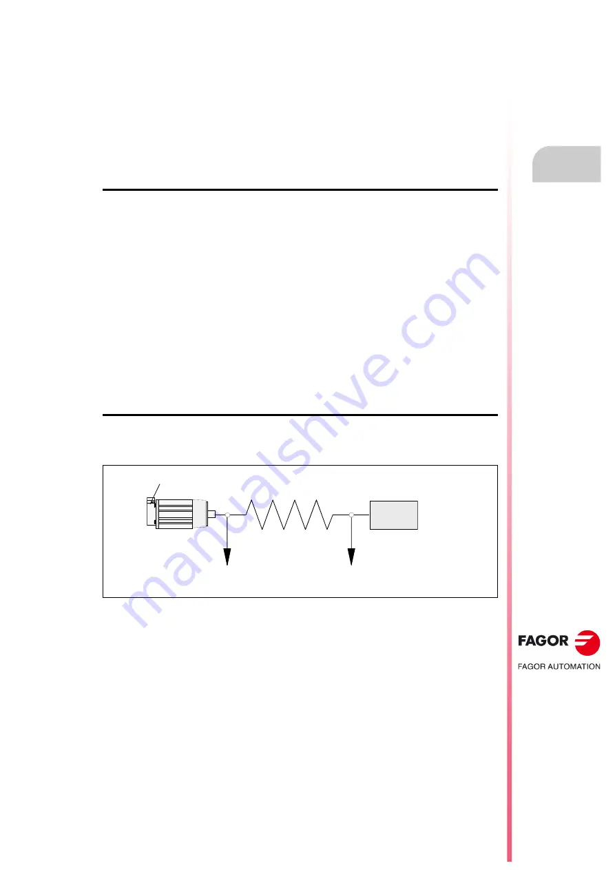
Elastic deformation in the coupling of an axis
Let us suppose a system consisting of a servomotor with a position feedback, an elastic coupling
and the tool tip..
When the system starts moving, if the coupling would ideally not be deformed, the position of the
tool tip would strictly follow the path that the part program of the CNC commanded and it would be
the same as the position given by the feedback device integrated into the motor.
However, assuming that the coupling cannot be deformed is not realistic Therefore, while moving,
the coupling suffers an elastic deformation more or less significant depending on its acceleration;
i.e. of the relative feedrate between the tool tip and the table that affects, to a greater or lesser degree.
the path to follow.
Then, the path demanded by the part-program of the CNC is not truthfully followed by the tool tip,
there is a deviation due to the elastic deformation of the axis coupling.
This path deviation is not measured by the motor position feedback device because it is located just
before the elastic coupling and, consequently, it is not aware of this deformation. This is why there
is no deviation to compensate for the control loop of the CNC.
In this scenario where this deviation is not measured and, even if it is, it cannot be compensated
for by increasing the proportional gain of the system in the control loops, this deviation must be
compensated using the axis parameter DYNDEFRQ (P103), setting it with the value of the
MOTOR
FEEDBACK
ELASTIC
COUPLING
MEASURED AT THE
MOTOR FEEDBACK
MEASURED AT THE
TOOL TIP
MOTOR
LOAD
k,m
Summary of Contents for CNC 8055i
Page 1: ...CNC 8055 Installation manual Ref 1705 Soft V02 2x...
Page 8: ...8 Installation manual CNC 8055 CNC 8055i SOFT V02 2X...
Page 12: ...18 CNC 8055 CNC 8055i Declaration of conformity and Warranty conditions...
Page 16: ...10 CNC 8055 CNC 8055i Version history...
Page 22: ...16 CNC 8055 CNC 8055i Returning conditions...
Page 24: ...20 CNC 8055 CNC 8055i Additional notes...
Page 26: ...22 CNC 8055 CNC 8055i Fagor documentation...
Page 72: ...72 Installation manual CNC 8055 CNC 8055i 1 8055 CNC CONFIGURATION SOFT V02 2X Operator panel...
Page 227: ...Installation manual CNC 8055 CNC 8055i MACHINE PARAMETERS 6 SOFT V02 2X 227 Axis parameters...
Page 290: ...290 Installation manual CNC 8055 CNC 8055i 6 MACHINE PARAMETERS SOFT V02 2X Tables...
Page 474: ...474 Installation manual CNC 8055 CNC 8055i 10 PLC PROGRAMMING SOFT V02 2X PLC library...
Page 644: ......
Page 652: ...652 Installation manual CNC 8055 CNC 8055i B SOFT V02 2X Central unit of the 8055 CNC...
Page 654: ...654 Installation manual CNC 8055 CNC 8055i C SOFT V02 2X 11 LCD Monitor...
Page 656: ...656 Installation manual CNC 8055 CNC 8055i D SOFT V02 2X Probe connection at the 8055i...
Page 658: ...658 Installation manual CNC 8055 CNC 8055i E SOFT V02 2X Probe connection at the 8055 CNC...
Page 681: ...Installation manual CNC 8055 CNC 8055i J SOFT V02 2X 681 Key code MC operator panel...
Page 682: ...682 Installation manual CNC 8055 CNC 8055i J SOFT V02 2X Key code...
Page 683: ...Installation manual CNC 8055 CNC 8055i J SOFT V02 2X 683 Key code TC operator panel...
Page 684: ...684 Installation manual CNC 8055 CNC 8055i J SOFT V02 2X Key code...
Page 685: ...Installation manual CNC 8055 CNC 8055i J SOFT V02 2X 685 Key code MCO TCO operator panel...
Page 686: ...686 Installation manual CNC 8055 CNC 8055i J SOFT V02 2X Key code Alphanumeric keyboard...
Page 687: ...Installation manual CNC 8055 CNC 8055i J SOFT V02 2X 687 Key code 11 LCD Monitor...
Page 688: ...688 Installation manual CNC 8055 CNC 8055i J SOFT V02 2X Key code...
Page 692: ...692 Installation manual CNC 8055 CNC 8055i K SOFT V02 2X Logic outputs of key status...
Page 694: ...694 Installation manual CNC 8055 CNC 8055i K SOFT V02 2X Logic outputs of key status...
Page 698: ...698 Installation manual CNC 8055 CNC 8055i K SOFT V02 2X Logic outputs of key status...
Page 702: ...702 Installation manual CNC 8055 CNC 8055i L SOFT V02 2X Key inhibiting codes...
Page 704: ...704 Installation manual CNC 8055 CNC 8055i L SOFT V02 2X Key inhibiting codes...
Page 707: ...Installation manual CNC 8055 CNC 8055i L SOFT V02 2X 707 Key inhibiting codes 11 LCD Monitor...
Page 708: ...708 Installation manual CNC 8055 CNC 8055i L SOFT V02 2X Key inhibiting codes...
Page 722: ...722 Installation manual CNC 8055 CNC 8055i N SOFT V02 2X M functions setting chart...
Page 728: ...728 Installation manual CNC 8055 CNC 8055i Q SOFT V02 2X Maintenance...
Page 729: ...Installation manual CNC 8055 CNC 8055i Q SOFT V02 2X 729...
Page 730: ...730 Installation manual CNC 8055 CNC 8055i Q SOFT V02 2X...
Page 731: ......


