background image

16

+

ENGLISH

In STAND BY (gate closed and in stand-by) with 

BUS-2EASY


Encoder

 on leaf 1 and leaf 2 and 

BUS-2EASY


Photocells

 correctly connected and entered.

In case of 

BUS-2EASY


Encoder

 on leaf1 and leaf 2 and 

BUS-2EASY


Photocells 

correctly con-

nected and entered and with closing photocells engaged:

Encoder on leaf 1 cor-

rectly entered

Encoder on leaf 2 cor-

rectly entered

at least one pair of opening 

photocells correctly entered

at least one pair of closing  

photocells correctly entered

Fig. 

examples of 

BUS-2EASY

 status visualization on display.

CHECKING THE SECURING DEVICES ENTERED ON THE BOARD

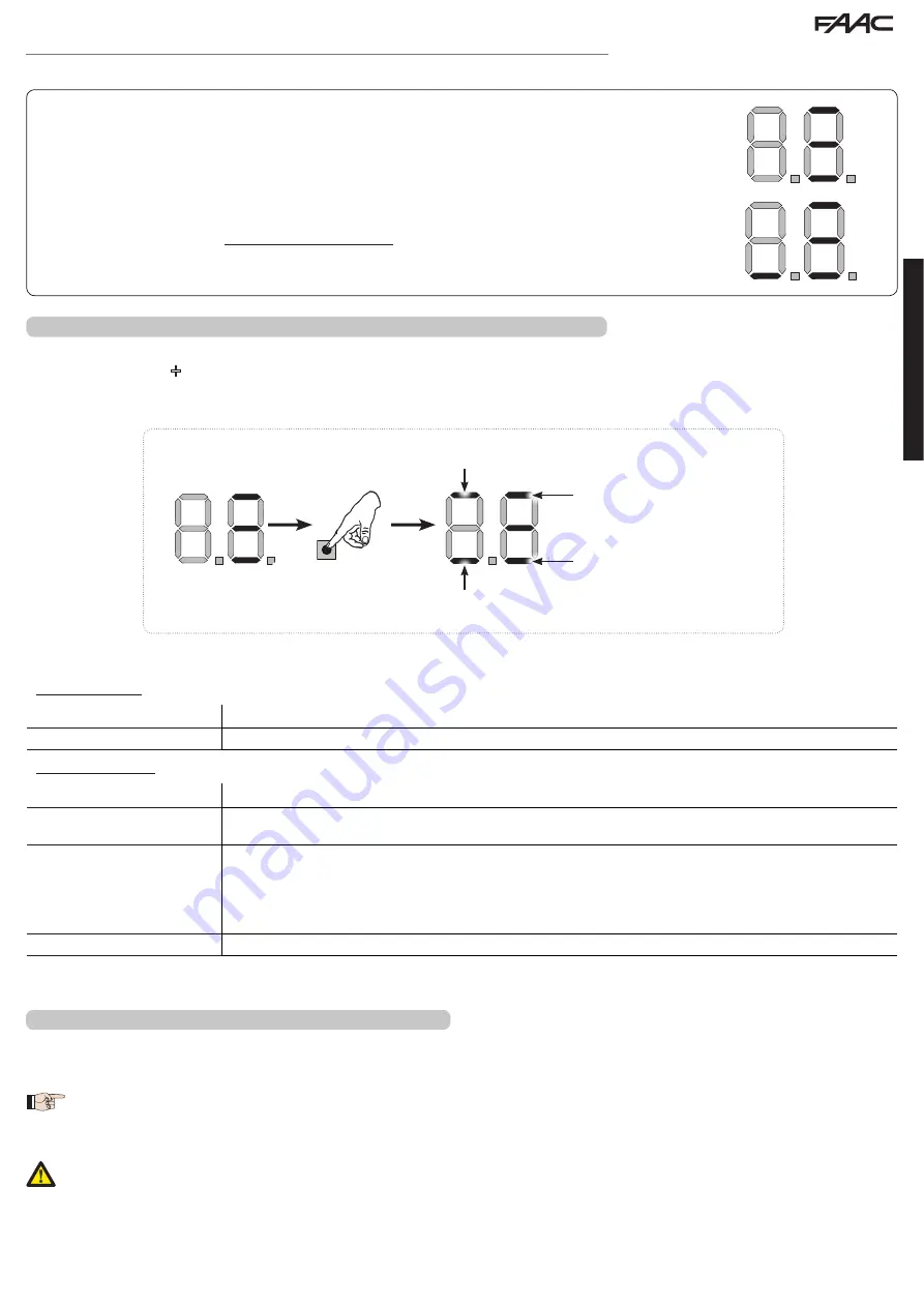
To verify the types of BUS device recognised through the entry:
1.  Press and hold the 

+

 button during stand-by visualisation; the segments corresponding to at least one entered device will go ON. E.g.:

To check the condition of the 

BUS-2EASY

 connection, verify the LED on the board:

LED DL15 (Red)

ON

Safety device engaged or pulse generator active

OFF

NO safety device engaged neither pulse generator active

LED DL14 (Green)

ON steady

Normal activity (led ON even if there are no devices).

Slow blinking (blink every 

2,5 sec)

BUS-2EASY

 line short-circuit.

Rapid blinking (blink every 

0.5 sec)

Error in the 

BUS-2EASY

 connection.

Repeat the device entry. If the error occurs again, check:
 - That there are no more than one device in the system with the same address.
 - Calling error (number > or < the connected BUS devices).
 - FAIL SAFE error on the BUS device.

OFF

Board in Sleep mode (if used).

TIME LEARNING - SETUP

When the board is powered, if a SETUP has never been performed, or if the board requests it, on the display 

S0

 indicates that a SETUP must 

be performed.

 During SETUP, the connected 

BUS-2EASY

 accessories are always entered. The 

BUS-2EASY

 encoders entered by the SETUP 

must always be enabled using the parameter 

En

 (BASIC Programming).


If a system without an encoder is installed, mechanical stops will be required for the leaves.

  During SETUP all safety devices are disabled! Therefore, carry out the operation avoiding any transit in the leaf movement 

area.

Summary of Contents for E124

Page 1: ...E124 ...

Page 2: ...er Battery Decoder Minidec RP X COM module XF433 868 USB Terminal board inputs BUS 2EASY Inputs from IN1 to IN5 Travel limit device Encoder Terminal board outputs Flashing lamp Motors Electrical lock OUT1 OUT2 programmable power feed to accessories Programming 1st and 2nd lev with 3 keys F and LCD display 3rd lev with PC connected via USB TECHNICAL SPECIFICATIONS WARNINGS Important For the safety ...

Page 3: ...PUTSTATUSCONTROLLED ENC1 Gatecoder DL11 INPUTSTATUSCONTROLLED ENC2 Gatecoder DL12 LEDFORDEVICEBUS 2EASYACTIVE DL13 LEDFORBUS2 EASYDIAGNOSTICS DL14 LEDSIGNALLINGPRIMARYPOWERON DL15 LEDSIGNALLINGSECONDARYPOWERON DL16 LEDFOR SW1 PUSH BUTTON R1PUSH BUTTON DL17 LEDFOR SW2 PUSH BUTTON R2PUSH BUTTON DL18 LEDFOR SW3 PUSH BUTTON SETUPPUSH BUTTON DL19 PRESSURESIGNALLINGLED RESETSW PUSH BUTTON DL20 ALARMSIGN...

Page 4: ...ching selector to its correct position Default 230 V To ensure correct operation the switching feeder must be connected to the earth conductor in the system Install an adequate differential thermal breaker upstream of the system SECONDARY POWER FEED J2 In the absence of a primary feed from the mains the control unit can be fed by a secondary low voltage 24V power feed Power can be supplied by a pa...

Page 5: ...er Make sure that there are not two or more photocell pairs with the same address If you are not using any BUS 2EASY accessory leave free connector BUS 2EASY PHOTOCELLS BUS 2EASY DL1 Alignment DL2 BUS 2EASY power supply status DS1 Programming dip switches Dip1 Dip2 Dip3 Dip4 Rif Type OFF OFF OFF OFF B C OPENING OFF OFF OFF ON OFF OFF ON OFF OFF OFF ON ON OFF ON ON OFF OFF ON ON ON ON OFF OFF OFF D...

Page 6: ...L2 DL3 DL1 DL2 DL3 HDI RSHQV DV UVW DQG FORVHV DV VHFRQG BUS 2 EASY ENCODER CONNECTION 1 Connect the 2 encoder cables to the BUS 2EASY input red terminal on the board 2 Check that the encoder is connected correctly according to the table The LEDs must be checked with the leaf stopped If necessary swap the 2 connecting wires to obtain the correct coupling of the encoder with the leaf as indicated i...

Page 7: ...e The default password is 0000 The programming using a PC MAC with a modified PASSWORD different from the default one will inhibit the programming by board If one of the buttons is pressed the display will show PC programming for 5 sec and changes will be allowed only by PC MAC 쐃 쐇 쐋 BASIC PROGRAMMING 1A PRESS AND HOLD F THE FIRST FUNCTION APPEARS Í 1 RELEASE F THE FUNCTION VALUE IS DISPLAYED USIN...

Page 8: ...tors FAAC S450H see column cF 5 6 Configures the parameters with DEFAULT values corresponding to an installation with operators FAAC S800H ENC see column cF 6 PC Mixed configuration from a PC MAC At the time of changing the set motor type on the board the relevant defaults are uploaded 0 1 2 4 3 6 5 dF DEFAULT Y indicates that all the set values correspond to the default values no indicates that o...

Page 9: ...ing the SETUP with two motors or by returning to one motor If a SETUP is performed with two motors and later only one is used the board will not signal an error Only the motor connected to input M1 will move When programming from a PC MAC you can select different partial openings 02 02 02 02 F1 MOTOR 1 POWER You can adjust the maximum power of motor 1 which is the same during both opening and clos...

Page 10: ...ts you set or disable use of the closing limit switch on swing leaves no closing limit switches disabled 0 1 the limit switch determines the stopping of motion 02 the limit switch determines the start of deceleration After having changed the value of this function SETUP is required the card will signal error 14 configuration error until the SETUP is performed again or until the previous value is r...

Page 11: ...guration you just performed 1 set the choice Y to SAVE and EXIT the programming no to EXIT the programming WITHOUT SAVING 2 press the button F to confirm at the end the display returns to visualize the automated system status Y 00 CLOSED 01 OPEN 02 Stationary then OPENS 03 Stationary then CLOSES 04 In PAUSE 05 during Opening 06 during Closing 07 FAIL SAFE in progress 08 checking BUS 2EASY devices ...

Page 12: ...ing to open the motors give a brief push to close Y enabled for 2 sec no disabled In case of systems with an absolute encoder to enable this function a setup must be performed using the automatic leaf stop on the mechanical contact point no no no no EL ELECTRIC LOCK ON LEAF 2 The board has a terminal dedicated to the connection of an electric lock Normally the electric lock must be connected to le...

Page 13: ... disabled no no no no EC ANTI CRUSHING SENSITIVITY Varying this function varies the amount of time after which in case of obstacle the board commands reversal of the leaves or it will command a stop if the leaves are in the contact point search space see the pa rameter rB The fourth consecutive obstacle detected in the same direction and posi tion will be defined as a contact point and the leaf wi...

Page 14: ...MERGENCY 09 automated system in OPENING 10 automated system in CLOSING 1 1 electric lock control before OPENING and before CLOSING 12 safety device ACTIVE 13 TRAFFIC LIGHT function active when OPENING and with automated system OPEN 14 timed output which can be activated from the second radio channel OMNIDEC see function t1 15 output which can be activated from the second radio channel OMNIDEC step...

Page 15: ...ill display 65 and 53 respectively no no no no nc CYCLE PROGRAMMING THOUSANDS If AS Y the display will show the number of thousands of cycles after which the signaling of maintenance request begins can be set from 0 to 99 If AS no the display will show the number of thousands of work cycles performed The value displayed is updated with the succession of the cycles interacting with the value in nd ...

Page 16: ...ice has ever been entered in the board the display will read no Encoder 1 ON correctly connected and entered Encoder 2 ON correctly connected and entered BUS Status always ON OPEN photocell ON entered and engaged Opening photocells ON entered and engaged Closing photocells ON entered and engaged Fig Visualising the BUS 2EASY status in the function bu each segment of the display shows one type of d...

Page 17: ... or pulse generator active OFF NO safety device engaged neither pulse generator active LED DL14 Green ON steady Normal activity led ON even if there are no devices Slow blinking blink every 2 5 sec BUS 2EASY line short circuit Rapid blinking blink every 0 5 sec Error in the BUS 2EASY connection Repeat the device entry If the error occurs again check That there are no more than one device in the sy...

Page 18: ... 2 begins closing Operation WITHOUT Safecoder Leaf 2 automatically acknowledges the mechanical stop Operation WITH Safecoder or S800H ENC Leaf 2 automatically acknowledges the mechanical stop It will in any case be possible to stop leaf movement at any time and in the desired point by sending an OPEN A pulse 7 On the display S4 flashes leaf 1 begins closing Operation WITHOUT Safecoder Leaf 1 autom...

Page 19: ...e Other more detailed programming options are available using a PC MAC see dedicated PC MAC instructions For example you can set an automatic OPEN command on the radio channel to command an automatic cycle open pause close regardless of the selected logic MEMORISING THE SLH SLH LR RADIO CONTROLS 1 Press and hold OPEN A programming or OPEN B CLOSE programming 2 After keeping the button pressed for ...

Page 20: ... 20 sec 3 Release the button 4 During radio LED flashing press the desired button of the LC RC radio control 5 The corresponding LED on the board DL11 or DL12 will go on steady for 1 second indicating that memorisation has been completed and will begin flashing again for another 20 sec during which you can memorise another radio control 6 When the 20 sec have elapsed the LED will turn off indicati...

Page 21: ...e board DL11 or DL12 will go on steady for 1 second and then go off indicating that memorisation has been completed 7 To add other different codes repeat the procedure starting from point 1 8 To add other radio controls with the same code set the 12 dip switches according to the same combination as the already memorised radio control DELETING THE RADIO CONTROLS This operation CANNOT be reversed Th...

Page 22: ...ult Check the connections or replace motor 2 encoder 1 9 Incorrect memory data Repeat BUS 2EASY device entry and or re program the board 4 5 Battery operation No action required 9 3 High absorption at 24V Check that absorption by the accessories connected is within permitted limits N ALARM Solution Description 2 0 Obstacle on MOTOR 1 only with en coder Remove any possible obstacle on leaf 1 2 1 Ob...

Page 23: ......

Page 24: ...5679 6645 faactm info faacgroup com www faac de INDIA FAAC INDIA PVT LTD Noida Delhi India tel 91 120 3934100 4199 www faacindia com IRELAND NATIONAL AUTOMATION LIMITED Boyle Co Roscommon Ireland tel 353 071 9663893 www faac ie MIDDLE EAST FAAC MIDDLE EAST FZE Dubai Silicon Oasis free zone tel 971 4 372 4187 www faac ae NORDIC REGIONS FAAC NORDIC AB Perstorp Sweden tel 46 435 779500 www faac se PO...

Reviews: