
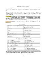
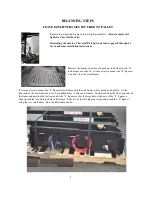

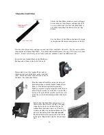

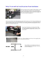


Note the illustration to the left. The large pre-
drilled holes are used to attach the frame to the
wheel well with 5/16” screws at a later stage in the
installation. The small holes are used, along with
the self tapping screws, to attach the “L” Spacer to
the unit frame before installation.
6
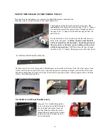
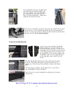
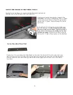
The installation of the Boom Arm Frames after the mounting of the “L” Spacers will differ slightly for the
Dodge, Ford and Toyota and for the Chevrolet pick up trucks. The installation instructions for the Chevro-
let trucks are found in a separate section beginning on the next page and continuing through page 13.
Pages 8 through 13 will apply to Chevrolet trucks only.
If installing the Boom Arm Frames for a Dodge, Ford or Toyota, please turn to page 14 of the manual and
continue the installation.
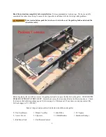
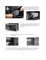
The installation will be done in four steps:
•
Measure the wheel well distance and determine the need for the “L” Spacer and, if needed, mount the
“L” Spacer. Leave the unit Boom Arm Frames attached to the pallet but unpack the rest of the pieces
and make sure that they are all there. (Refer to the list on page 4)
•
Installation of the unit Arm Frames to the truck bed
•
Running and connecting the Hydraulic Hoses and Electrical Cords
•
Mounting of the Winch Crossbar and connecting the Winch Electrical Leads


