


IN1604 DTP and IN1604 HD Scalers • Configuration Software
74
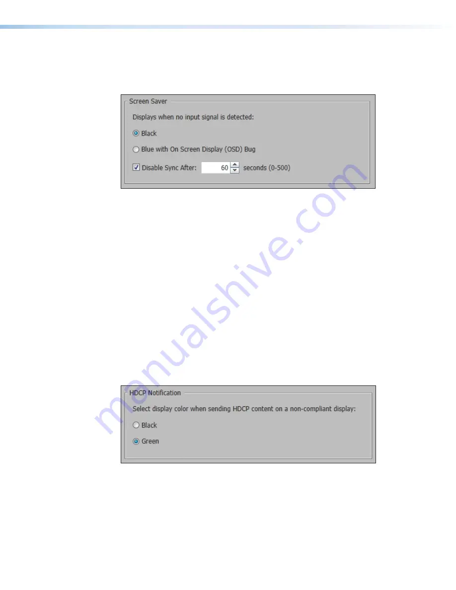
Screen Saver panel
When no active video is detected on the selected input, the screen saver mode is activated.
The output sync can be disabled after a user-set duration, which allows display devices to
go into a low power, standby state.
Figure 55.
Screen Saver Panel
1.
Click one of the radio buttons to select a display when the screen saver is enabled.
•
Black
— Mutes video output to black for a set duration before disabling output
sync (default).
•
Blue with On Screen Display (OSD) Bug
— Displays a blue background with
a moving OSD message that indicates “<
scaler model
>
: Input
<
number
>
No
Signal
” for a set duration before disabling the output sync.
2.
Select a duration to display the screen saver before the output sync is disabled.
•
Select the
Disable Sync After
check box to disable the scaler output sync after
a set duration without an active input. When selected, the
Duration On Screen
field becomes available.
•
In the
Duration
field, enter a value in the field or click the
Up
and
Down
arrows to
specify a duration to wait before disabling output sync during inactivity. The default
is to never disable the output sync.
HDCP Notification panel
HDCP notification indicates when HDCP content restrictions prevent a video signal from
passing.
Figure 56.
HDCP Notification Panel
Select one of the following radio buttons:
•
Black
— Displays a black or muted screen when an encrypted source is sent to a
display that is not HDCP-compliant.
•
Green
— Displays a green screen when an encrypted source is displayed on a sink that
is not HDCP-compliant (default).


