


DTP2 R 212 Series • Operation
18
Operation
This section describes the operation of the DTP2 R 212 switching receiver.
Topics include:
•
•
•
•
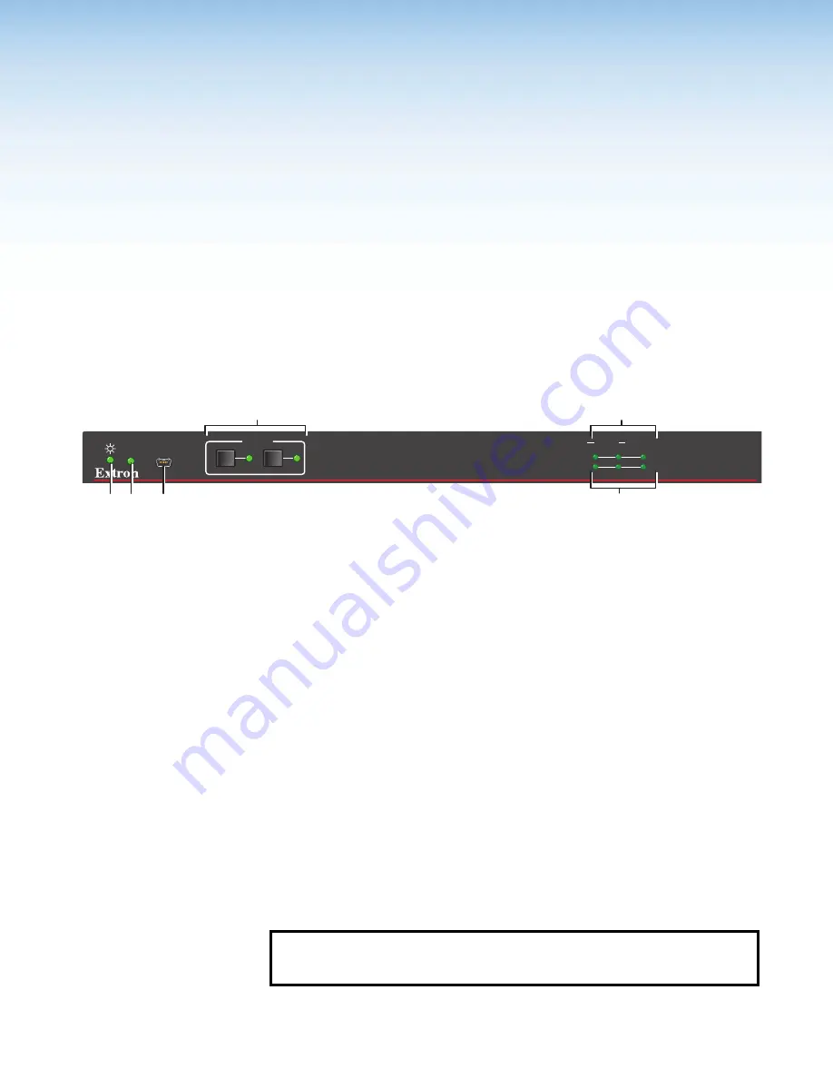
Front Panel Features
DTP2 R 212 SERIES
CONFIG
AUTO
SWITCH
INPUTS
OUTPUT
1
2
SIGNAL
HDCP
INPUTS
1
MODE
NORM/AUTO
2
A B
C
F
D
E
A
Power indicator LED
Input selection buttons and LEDs
B
Auto Switch LED
Signal Status LEDs
C
USB Config port
Figure 13.
Front Panel Features
A
Power indicator LED
— Lights when power is on.
B
Auto Switch LED
— Lights when Auto Switch is enabled.
C
USB Configuration port
— Connect a USB cable (USB A to mini‑B) between your
computer and this female USB mini‑B port to configure and control the switcher via SIS
commands or Product Configuration Software (PCS) and to update the firmware (see
D
Input selection buttons and LEDs
— Press one of these buttons to select an input to
switch to the output. The LED at the right of each button lights when the corresponding
input is selected.
If auto‑input switching is in effect, these buttons are disabled, but the LEDs continue to
light to indicate the selected input (see
for the procedure to set up automatic input selection or the SIS command
Signal status LEDs
•
Inputs
— Each input has a corresponding Signal LED which lights when a source
is connected to the input port and TMDS clock activity is detected on it.
NOTE:
If the source device connected to the selected input is HDCP encrypted
(requires HDCP authentication), the corresponding signal LED may not light
unless HDCP has been authenticated.
13
Summary of Contents for DTP2 R 212 Series
Page 2: ...Safety Instructions...
Page 6: ......


