18
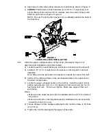
b) If the ends of the levers hit against each other, while in the drive position (levers
rotated in as far as possible), make adjustments by moving the levers outwards
to the neutral lock position and carefully bending them outward. Move them
back to the drive position and check for clearance, repeat if necessary.
3.9 POSITION DISCHARGE CHUTE
3.9.1
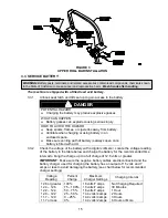
Loosen two (2) 5/16” nyloc nuts attaching discharge chute. Lower the discharge
chute into position. Retighten nyloc nuts until chute is snug but can pivot freely.
3.10 SERVICE ENGINE
Refer to Engine Owner’s Manual.
3.11 SERVICE HYDRAULIC OIL
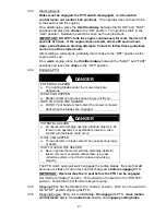
The machine is shipped with hydraulic oil in the reservoir. Run the machine for
approximately 15 minutes to allow any extra air to purge out of the hydraulic
system. Check hydraulic reservoir and if necessary fill the reservoir to the
appropriate level with Mobil 1 15W-50 synthetic motor oil. Replace hydraulic
reservoir cap and tighten until snug.
Do not overtighten.
NOTE: The baffle is labeled “HOT” and “COLD”. The oil level varies with the
temperature of the oil. The “HOT” level shows the level of oil when it is at 225°F
(107°C). The “COLD” level shows the level of the oil when it is at 75°F (24°C).
Fill to the appropriate level depending upon the temperature of the oil. For
example: If the oil is about 150° F (65°C). Fill to halfway between the “HOT” and
“COLD” levels. If the oil is at room temperature (about 75° F (24°C)), fill only to
the “COLD” level.
4. OPERATION INSTRUCTIONS
4.1 CONTROLS
4.1.1
Familiarize yourself with all controls before operating the mower.
4.1.2
Motion Control Levers: Located on each side of the console.
The left lever controls the flow of hydraulic oil from the left hydrostatic pump to
the left drive wheel motor. The right lever controls the flow of hydraulic oil from
the right hydrostatic pump to the right drive wheel motor.
IMPORTANT: To begin movement (forward or backward) the operator must
be in the seat, the brake lever must be disengaged (pushed down) before
the motion control levers can be moved in or the engine will kill.
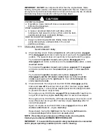
When levers are centered in the T-slot the drive system is in the neutral position.
With levers moved out in the T-slot the drive system is in the
neutral lock
position (See Figure 7).
FIGURE 7
MOTION CONTROL POSITIONS
By moving both levers an
equal
amount forward or back from the neutral position
the machine can be caused to move forward or backward in a straight line.
Movement of the
left lever forward
will cause the
left drive wheel
to rotate in a
forward direction. Movement of the
right lever forward
will cause the
right
drive wheel
to rotate in a forward direction. To
stop
forward travel, pull the
levers back to the neutral position.
Summary of Contents for Laser Z CT
Page 1: ...For Serial Nos 540 000 Higher Part No 103 9180 ...
Page 45: ...40 8 BRIGGS STRATTON ELECTRICAL DIAGRAM ...
Page 46: ...41 9 HYDRAULIC DIAGRAM ...
Page 48: ... 43 NOTES ...
Page 49: ... 44 NOTES ...
Page 50: ... 45 SERVICE RECORD Date Description of Work Done Service Done By ...
Page 51: ... 46 ...


