16
CAUTION
POTENTIAL HAZARD
♦
If the ignition is in the “ON” position there is potential
for sparks and engagement of components.
WHAT CAN HAPPEN
♦
Sparks could cause an explosion or moving parts
could accidentally engage causing personal injury.
HOW TO AVOID THE HAZARD
♦
Be sure ignition switch is in the “OFF” position before
charging the battery.
3.3.3
Connect the negative battery cables.
NOTE:
If the positive cable is also disconnected, connect the
positive (red)
cable
to the positive battery terminal
first
, then the negative (black) cable and
green/white wire to the negative battery terminal. Slip insulator boot over the
positive terminal.
NOTE:
If time does not permit charging the battery, or if charging equipment is
not available, connect the negative battery cables and run the vehicle
continuously for 20 to 30 minutes to sufficiently charge the battery.
3.4 INSTALL DRIVE WHEELS
3.4.1
Mount drive wheels with the valve stem to the outside of the unit. Secure using
four (4) 1/2-20 wheel nuts (installed on studs in hubs) for each wheel. Torque to
95 ft-lbs (128 N
x
M).
3.5 CHECK TIRE PRESSURE
3.5.1
Check tire pressure in caster and drive tires. Proper inflation pressure for caster
tires is 16 psi (110 kPa). Proper inflation for drive tires is 13 psi (90 kPa). Adjust
if necessary.
3.6 CHECK PARK BRAKE
3.6.1
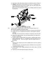
Disengage the park brake. Measure the distance vertically from the lower front
corner of the brake bar to the crown of the tire. The distance should measure 1”
(2.5 cm) to 1 5/16”(3.3 cm). To adjust the brake, loosen the jam nuts next to the
yoke at each end of the park brake linkage. Place a wrench on one of the two
nuts near the front of the park brake linkage. Turn the linkage until the distance
from the lower front corner of the brake bar measured vertically to the crown of
the tire is 1” (2.5 cm) to 1 5/16” (3.3 cm) with the park brake disengaged. Re-
tighten the jam nuts. See Figure 4.
Summary of Contents for Laser Z CT
Page 1: ...For Serial Nos 540 000 Higher Part No 103 9180 ...
Page 45: ...40 8 BRIGGS STRATTON ELECTRICAL DIAGRAM ...
Page 46: ...41 9 HYDRAULIC DIAGRAM ...
Page 48: ... 43 NOTES ...
Page 49: ... 44 NOTES ...
Page 50: ... 45 SERVICE RECORD Date Description of Work Done Service Done By ...
Page 51: ... 46 ...


