13
2.10.4
Tread Width: (center to center of tires, widthwise)
44” Deck
48” Deck
52” Deck
Drive Wheels
34.9 in. (88.6 cm)
34.9 in. (88.6 cm)
34.9 in. (88.6 cm)
Front Casters
32.7 in. (83.1 cm)
32.7 in. (83.1 cm)
34.1 in. (86.6 cm)
2.10.5
Wheel Base: (center of caster tire to center of drive tire)
44” Deck
48” Deck
52” Deck
46.2 in. (117.3 cm)
46.2 in. (117.3 cm) 46.2 in. (117.3 cm)
2.10.6 Curb Weight:
44” Deck
48” Deck
52” Deck
880 lbs. (399 kg)
910 lbs. (413 kg)
970 lbs. (440 kg)
2.11 TORQUE REQUIREMENTS
Bolt Location
Torque
Cutter Housing Spindle Nut (secured with threadlocker) 140-145 ft-lbs. (190-197 N-m)
Blade Mounting Bolt ................................................................ 55-60 ft-lbs. (75-81 N-m)
Engine Deck/Front Frame Mount Bolts ................................... 30-35 ft-lbs. (41-47 N-m)
Anti-Scalp Roller Nuts ............................................................. 40-45 ft-lbs. (54-61 N-m)
Engine Mounting Bolts ........................................................... 25-30 ft-lbs. (34-41 N-m)
Wheel Motor Mounting Bolts ................................................. 72-77 ft-lbs. (98-104 N-m)
Wheel Hub Slotted Nut .................................................. minimum 125 ft-lbs. (169 N-m)
Wheel Lug Nuts .................................................................. 90-95 ft-lbs. (122-129 N-m)
Rollover Protection System (roll bar) Mounting Bolts .............. 30-35 ft-lbs. (41-47 N-m)
Clutch Retaining Bolt (secured with threadlocker) ................... 55-60 ft-lbs. (75-81 N-m)
3. ASSEMBLY INSTRUCTIONS
3.1 UNCRATE MOWER
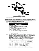
3.2 INSTALL ROLLOVER PROTECTION SYSTEM (ROLL BAR)
3.2.1
Disassemble roll bar from the crate.
a) Remove roll bar tubes from sides of crate and remove screws that attach the
wheel hub retaining plate to the bottom of the crate.
b) Remove the two brackets used to mount the bottom of the upper roll bar tube
to the crate. Remove the 1/2-13 x 3 1/4 capscrews and 1/2-13 hex flange
lock nuts from the two brackets at each end of the upper roll bar tube and
retain for later use.
3.2.2
Raise the rear of the unit and support it with jack stands or equivalent support.
CAUTION
POTENTIAL HAZARD
♦
Raising the rear of the unit for assembly relying solely
on mechanical or hydraulic jacks could be dangerous.
WHAT CAN HAPPEN
♦
The mechanical or hydraulic jacks may not be enough
support or may malfunction allowing the unit to fall,
which could cause injury.
HOW TO AVOID THE HAZARD
♦
DO NOT rely solely on mechanical or hydraulic jacks
for support. Use adequate jack stands or equivalent
support.
3.2.3
Remove the wheel nuts from both sides of the unit and retain for later use.
3.2.4
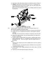
Install the two lower roll bar tubes.
a) Locate the left and right lower roll bar tubes.
Summary of Contents for Laser Z CT
Page 1: ...For Serial Nos 540 000 Higher Part No 103 9180 ...
Page 45: ...40 8 BRIGGS STRATTON ELECTRICAL DIAGRAM ...
Page 46: ...41 9 HYDRAULIC DIAGRAM ...
Page 48: ... 43 NOTES ...
Page 49: ... 44 NOTES ...
Page 50: ... 45 SERVICE RECORD Date Description of Work Done Service Done By ...
Page 51: ... 46 ...


