33
d)
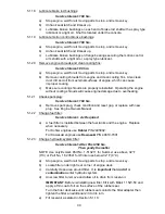
Set anti-scalp rollers to top holes or remove completely for this adjustment.
e)
Raise the deck to the 4.5” (11.4 cm) height position and take as much force
as possible off of the two large deck lift springs by loosening the nuts at the
front of each spring. See Figure 12.
f)
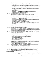
Lower the deck to the 1-1/2” (3.8 cm) height position. Place two 1-5/16”
(3.3 cm) thick blocks under the rear edge of the cutting deck skirt; one on
each side of the cutting deck. Place a 1-1/8” (2.9 cm) block under the
center front edge, but not under the anti-scalp roller brackets.
g)
Loosen the two (2) bottom chain bolts in slots at the rear of the cutting
deck. Loosen four (4) nuts which secure front swivels (two per side), until
front chains are loose and front of deck is supported by the 1-1/8” (2.9 cm)
block. Do not loosen front chain hardware.
h)
When hardware is loosened, remaining tension in the large support springs
will tend to rotate the deck lift handle up, out of the 1 1/2” (3.8 cm) position.
Press down on the rear deck support arm (as shown in Figure 7) to firmly
return the deck lift handle to the 1 1/2” (3.8 cm) position.
DO NOT
push on
deck lift handle. While continuing to press down,
take the slack out of the
rear chains and tighten hardware at the bottom of
the rear chains.
Downward pressure may now be released.
i)
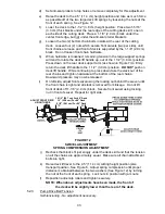
On left side, adjust front swivel using the locking nut behind the swivel until
the front chain is tight and all slack is removed from linkage. Do not lift
front of deck off 1-1/8” (2.9 cm) block. Secure front swivel using locking
nut in front of swivel. Repeat for right side.
FIGURE 12
SWIVEL ADJUSTMENT
SPRING COMPRESSION ADJUSTMENT
j)
Recheck that blocks fit just snugly under the deck skirt and that the tension
on all the chains are approximately equal. Make sure all chain attachment
bolts are tight.
k) Raise deck lift lever to the 4.5” (11.4 cm) cutting height position (also
transport position, See Figure 6. Adjust spring compression until proper
distance is obtained between the two washers (See Figure 12) by turning
the nut at the front of each spring. Lock nuts in position with jam nuts.
l)
Reposition anti-scalp rollers and tighten securely.
NOTE: When above adjustments have been made, the front of
the deck will be slightly lower than the rear of the deck.
5.2.3
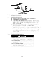
Pump Drive Belt Tension.
Self-tensioning - No adjustment necessary.
10 1/2" (26.7 cm) For 44” Deck
10” (25.4 cm) For 48” Deck
9 1/2" (24.1 cm) For 52” Deck
ADJUST FRONT DECK
HEIGHT HERE
Summary of Contents for Laser Z CT
Page 1: ...For Serial Nos 540 000 Higher Part No 103 9180 ...
Page 45: ...40 8 BRIGGS STRATTON ELECTRICAL DIAGRAM ...
Page 46: ...41 9 HYDRAULIC DIAGRAM ...
Page 48: ... 43 NOTES ...
Page 49: ... 44 NOTES ...
Page 50: ... 45 SERVICE RECORD Date Description of Work Done Service Done By ...
Page 51: ... 46 ...


