14
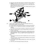
b) Align lower roll bar tubes along wheel motor channels as shown in Figure 2.
c)
LOOSELY
install lower roll bar hardware (four 3/8-16 x 1 capscrews, four
spring disk washers and four 3/8-16 whizlock nuts) from the bolt bag to the
tubes on each side as shown in Figure 2:
NOTE: Be sure the spring disk washer cone is installed towards the head of
the capscrew.
FIGURE 2
LOWER ROLL BAR INSTALLATION
3.2.5
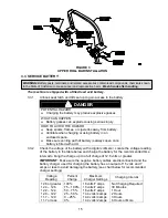
Install the upper u-shaped section of the roll bar. (Reference Figure 3 for
alignment and installation instructions below):
a) Locate the latch pin assemblies (pin and hairpin connected with a lanyard).
b) Install a 1/2-13 x 3 1/4 capscrew in the washer on the lanyard of each pin
assembly.
Note: Make sure the bent tab in the washer is towards the head of the bolt.
b)
Lightly oil the inside surfaces of the ear-shaped plates at the upper end of
the lower roll bar tubes.
c) Locate the upper u-shaped section of the roll bar. Install the upper roll bar
section using the two 1/2-13 x 3 1/4 capscrews from step b and two 1/2-13
hex flange lock nuts. Do not over tighten. Make sure upper roll bar can
pivot freely.
Notes:
•
Make sure the capscrew and nuts are installed with the nut to the inside of
the roll bar.
•
Make sure the tab on the lanyard washer is installed as shown and points
toward the front of the unit.
d) Torque all lower roll bar hardware attached to the machine frame to 30 ft-lbs.
(41-47 N-m).
e) Tighten the front knobs against the upper roll bar ends.
Summary of Contents for Laser Z CT
Page 1: ...For Serial Nos 540 000 Higher Part No 103 9180 ...
Page 45: ...40 8 BRIGGS STRATTON ELECTRICAL DIAGRAM ...
Page 46: ...41 9 HYDRAULIC DIAGRAM ...
Page 48: ... 43 NOTES ...
Page 49: ... 44 NOTES ...
Page 50: ... 45 SERVICE RECORD Date Description of Work Done Service Done By ...
Page 51: ... 46 ...


