


Multimeter Tests
120
MAX-635G
Voltage
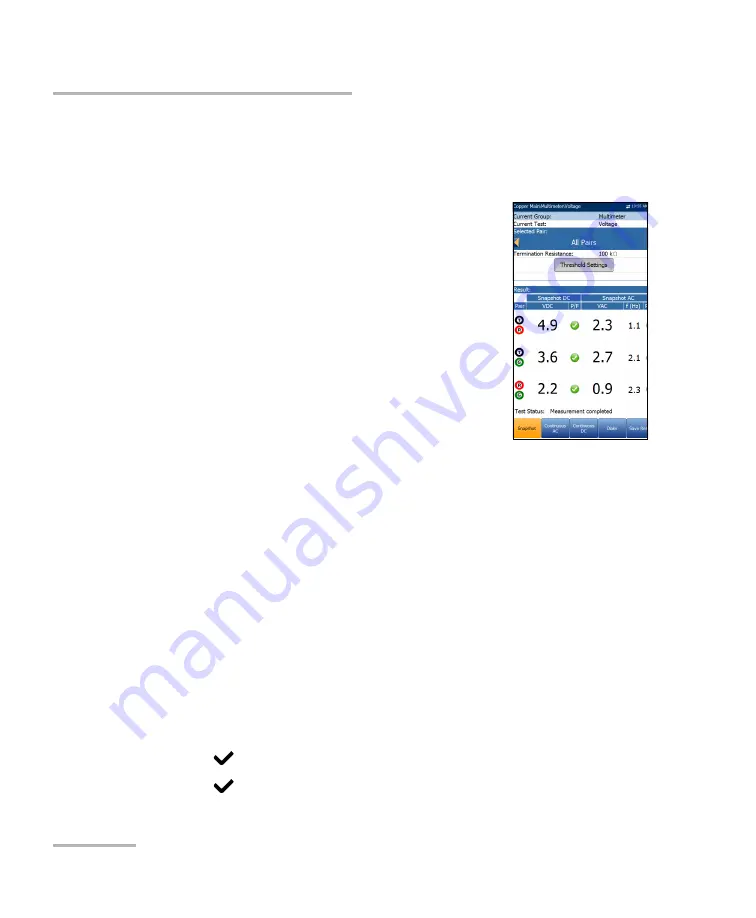
Snapshot
The voltage
Snapshot
tab shows measured volts for each lead
combination.
The parameters are as follows:
Current Group
is the current test group name, for
example
Multimeter
.
Current Test
displays the test being measured.
Here you can switch to another test from the given
list. However, this action will terminate the
ongoing measurement test.
Selected Pair
allows you to select
All Pairs
or a
single wire pair for measurement.
Termination Resistance
defines how much
resistance the tester uses to connect to the line
and measure voltages. The default value of
100 k
Ω
is widely used in
the industry.
Threshold Settings
button opens a new page that allows you to set the
AC/DC voltage thresholds for each pair.
Result
displays a snapshot of the pass/fail status, volts and
frequency (Hz) values for each continuous AC/DC pair.
Test Status
displays the current state of measurement or an error
message.
To select the parameter values:
1.
Press the up/down arrow keys to highlight the desired parameter.
2.
Press the left/right arrow keys to view and select the options.
OR
3.
Press
on a value to open a list box of options.
4.
Press
to confirm the value.
Summary of Contents for MAX-635G
Page 1: ...User Guide Copper and G fast VDSL2 ADSL2 Multi play Test Set MAX 635G www EXFO com ...
Page 10: ......
Page 26: ......
Page 162: ......
Page 218: ......
Page 270: ...TDR 260 MAX 635G Continuous Examples of Common Faults Short Fault ...
Page 271: ...TDR Copper and G fast VDSL2 ADSL2 Multi play Test Set 261 Continuous Open ...
Page 272: ...TDR 262 MAX 635G Continuous Bridged Tap ...
Page 273: ...TDR Copper and G fast VDSL2 ADSL2 Multi play Test Set 263 Continuous Splice Joint ...
Page 274: ...TDR 264 MAX 635G Continuous Peak Function ...
Page 275: ...TDR Copper and G fast VDSL2 ADSL2 Multi play Test Set 265 Continuous Dual Trace View ...
Page 276: ...TDR 266 MAX 635G Continuous Load Coil ...
Page 290: ......
Page 336: ......
Page 414: ......
Page 424: ......
Page 432: ......
Page 438: ......
Page 444: ......


