14
2.1
Video Connections, DVR cascading
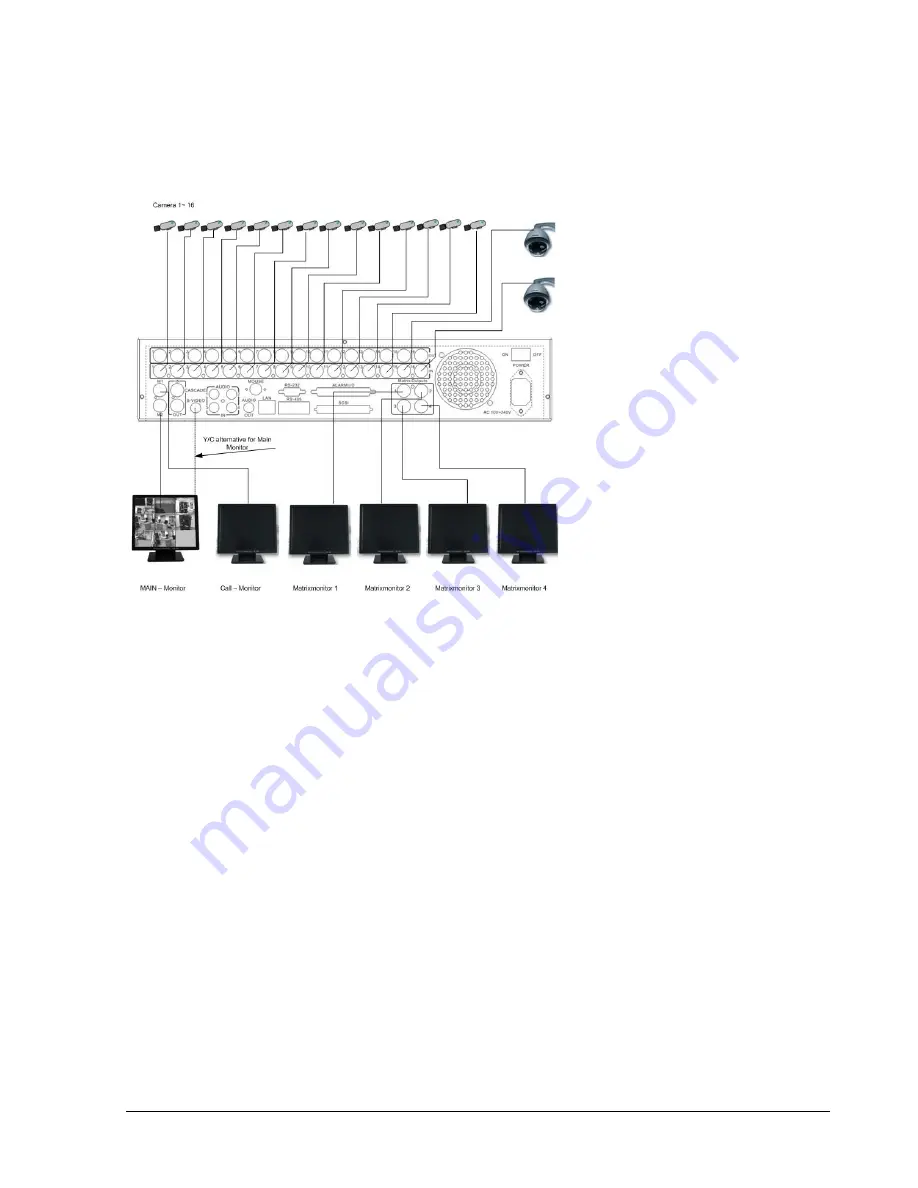
Sample installation with maximum camera and monitor configuration:
Diagram 2.3
Cameras and monitors have to be cabled with 75 Ohm video cable, e.g. RG-59, RG-6, RG-11 and
suitable BNC plugs.
Due to inappropriate absorbability, 50 Ohm coax cable (e.g. RG58), antenna cable and further types
of coax cable are not suitable.
All connected video sources must provide a 1 Vpp NTSC standard video signal.
When interconnecting transmission lines (twisted pair, fibre optics, radio) to the video inputs, ensure
the accurate receiver calibration.
The MAIN monitor may optionally be connected through a Y-C (S-Video) cable to achieve an
improved image quality.
For local DVR operation, MAIN monitor connection is compulsory. Call and matrix monitors can be
connected optionally.
ATTENTION: Make sure that there is a video signal on video input 1 upon start-up, as this input is
required for video system auto detection (NTSC/PAL)!
Summary of Contents for 920
Page 1: ...Instruction Manual E ED DR R1 16 64 40 0 1 16 62 20 0 9 92 20 0 ...
Page 99: ...89 ...
Page 100: ...90 ...
Page 101: ...91 ...
Page 104: ...94 ...
Page 138: ...128 CAMERA setup menu RECORD setup menu ALARM setup menu ...
Page 141: ...131 SCHEDULE setup menu CONTROL setup menu ...
Page 153: ...143 AppendixC AlarmBoardConfiguration Appendix C ...


