


Operating instructions
Non-Contact Safety System CES-A-UBA-01/CES-A-UBA-01B
8
(Translation of the original operating instructions) 2097097-17-08/20
6. Function
The safety system consists of three components:
Ì
Coded actuator
Ì
Read head
Ì
Evaluation unit
1 read head can be connected to the evaluation unit.
Each delivered actuator possesses a unique electronic coding and so is a unique element in the system used. The code in
an actuator cannot be reprogrammed.
Unlike systems with unique code detection, on multicode devices a specific code is not requested but instead it is only
checked whether the actuator is of a type that can be detected by the system (multicode detection). There is no exact
comparison of the actuator code with the taught-in code in the safety switch (unique code detection). The system possesses
a low coding level.
The read head is fastened to the fixed part of the guard and is connected to the evaluation unit via a two-core shielded cable
(terminals H11, H12 and SH1).
The actuator fastened to the movable part of the guard is moved towards the read head by closing the door. When the
switch-on distance is reached, power is supplied to the actuator by the read head by induction and data can be transferred.
If a permissible code is detected, the door monitoring output OUT (semiconductor output) is set to HIGH and the safety
outputs (relay output) are enabled. The OUT LED illuminates.
Due to the combination of dynamic polling of the actuators and the redundant, diverse design of the safety electronics with
redundantly controlled safety outputs, the evaluation unit will enter the safe state with every detectable fault.
When a guard is opened, the safety outputs switch off the safety circuit and the OUT LED goes out. The state of the safety
outputs is monitored internally by positively driven NC contacts (relay output).
Independent of the switching state of the safety circuit, the position of the safety door can be polled via the output OUT.
If an internal fault occurs in the evaluation unit, the safety circuit is switched off, the diagnostic output (ERR) is set HIGH
and the ERROR LED illuminates red.
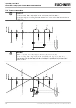
The safety contacts on the safety switch CES can also switch small currents. This allows the user to connect the device
directly to a safe control system.


