


Operating instructions
Non-Contact Safety System CES-A-UBA-01/CES-A-UBA-01B
18
(Translation of the original operating instructions) 2097097-17-08/20
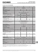
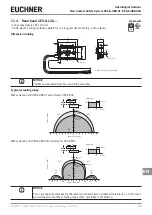
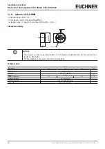
11.2. Read head CES-A-LNA-…
Ì
Cube-shaped design 42 x 25 mm
Ì
Hard-wired cable
Dimension drawing
CES-A-L XXXXXX
25
∅
8
∅
4,
5
42
32 ±0,1
12
4,6
"l"
2 M4 x 14 safety screws included
Active face
Active face
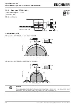
Typical actuating range
With evaluation unit CES-A-UBA-01 and actuator CES-A-BBA
-8
-4
-6
-2
2
6
4
8
0
2
4
6
8
Centre offset m [mm]
Distance s [mm]
OFF
ON
Actuator
Read head
s
m
Hysteresis
Switch-on
distance
ON
OFF
Hysteresis
Distance s
S
ao
Output stage
Switch-off
distance
OFF
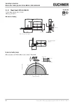
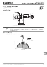
With evaluation unit CES-A-UBA-01B and actuator CES-A-BBA
Side
lobe
N
-10
-15
-5
0
Centre offset m [mm]
Distance s [mm]
OFF
ON
Switch-on
distance
ON
OFF
Hysteresis
Distance s
S
ao
Output state
Switch-off
distance
OFF
Hysteresis
-20
5
20
15
10
5
10
15
20
Side
lobe
N
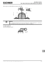
Actuator
Read head
s
m
NOTICE
For a side approach direction for the actuator and read head, a minimum distance of s = 3 mm must
be maintained so that the actuating range of the side lobes is not entered.
Approvals


