


17
2097097-17-08/20 (Translation of the original operating instructions)
Operating instructions
Non-Contact Safety System CES-A-UBA-01/CES-A-UBA-01B
EN
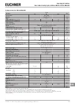
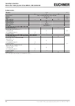
Technical data for CES-A-UBA-01B
Parameter
Value
Unit
min.
typ.
max.
Housing material
PA6.6 plastic
Dimensions
114 x 99 x 22.5
mm
Weight
0.2
kg
Ambient temperature at U
B
= DC 24 V
-20
-
+55
°C
Atmospheric humidity, not condensing
-
-
80
%
Degree of protection
IP20
Degree of contamination
2
Mounting
Mounting rail 35 mm according to EN 60715 TH35
Number of read heads
1 read head per evaluation unit
Connection (plug-in screw terminals/coded)
0.25
-
2.5
mm²
Operating voltage U
B
(regulated, residual ripple < 5%)
21
24
27
V DC
For the approval according to
the following applies
Operation only with UL class 2 power supply or equivalent measures
Current consumption I
B
(with relay energized)
1)
-
150
-
mA
External fuse (operating voltage U
B
)
0.25
-
8
A
Safety contacts
2 (relays with internally monitored contacts)
Switching current (relay outputs)
mA
- at switching voltage AC/DC 21 … 60 V
1
-
300
- at switching voltage AC/DC 10 … 30 V
10
-
6000
Switching load according to
Class 2 max. 30 V AC/Class 2 max. 60 V DC
120 V AC 3 A / 240 V AC 1.5 A
External fuse (safety circuit) according to EN 60269-1
6 AgG or 6 A circuit breaker (characteristic B or C)
Utilization category according to EN 60947-5-1
AC-12 60 V 0.3 A / DC-12 60 V 0.3 A
AC-12 30 V 6 A / DC-12 30 V 6 A
AC-14 30 V 2 A / DC-13 24 V 3 A
Rated insulation voltage U
i
63
V
Rated impulse withstand voltage U
imp
1.5
kV
Rated conditional short-circuit current
100
A
Resilience to vibration
Acc. to EN 60947-5-2
Mechanical operating cycles (relays)
10 x 10
6
Switching delay from state change
2)
-
-
180
ms
Discrepancy time (of the switching points of both relays)
-
-
120
ms
Ready delay
3)
-
-
3
s
Dwell time
4)
0.5
-
-
s
Switching frequency max.
5)
-
-
1
Hz
Repeat accuracy R acc. to EN IEC 60947-5-3
≤
10
%
Monitoring outputs (diagnostics ERR, door monitoring output
OUT, semiconductor output, p-switching)
6)
- Output voltage
0.8 x U
B
-
U
B
V DC
- Max. load
-
-
20
mA
Test input TST
- Input voltage
LOW
0
-
2
V DC
HIGH
15
-
U
B
- Input current
HIGH
5
8
10
mA
EMC protection requirements
Acc. to EN 60947-5-3
Reliability values acc. to EN ISO 13849-1
as a function of the switching current at 24 V DC
≤
0.1 A
≤
1 A
≤
3 A
Category
3
Performance Level (PL)
e
PFH
D
4.3 x 10
-8
Mission time
20
years
Number of switching cycles/year
760 000
153 000
34 600
Diagnostic coverage DC
90
%
MTTF
D
100
years
1) Without taking into account the load currents on the monitoring outputs.
2) Corresponds to the risk time according to EN 60947-5-3. This is the maximum OFF time for the safety outputs following removal of the actuator.
3) After the operating voltage is switched on, the relay outputs are switched off and the door monitoring output is set to LOW potential during the ready delay.
4) The dwell time of an actuator inside and outside the actuating range must be at least 0.5 s to ensure reliable detection of internal faults in the evaluation unit (self-monitoring).
5) If the current load is > 100 mA, a switching frequency of 0.1 Hz should not be exceeded as this will affect the mechanical life of the relay contacts.
6) Not short circuit-proof.


