1
Operation
9
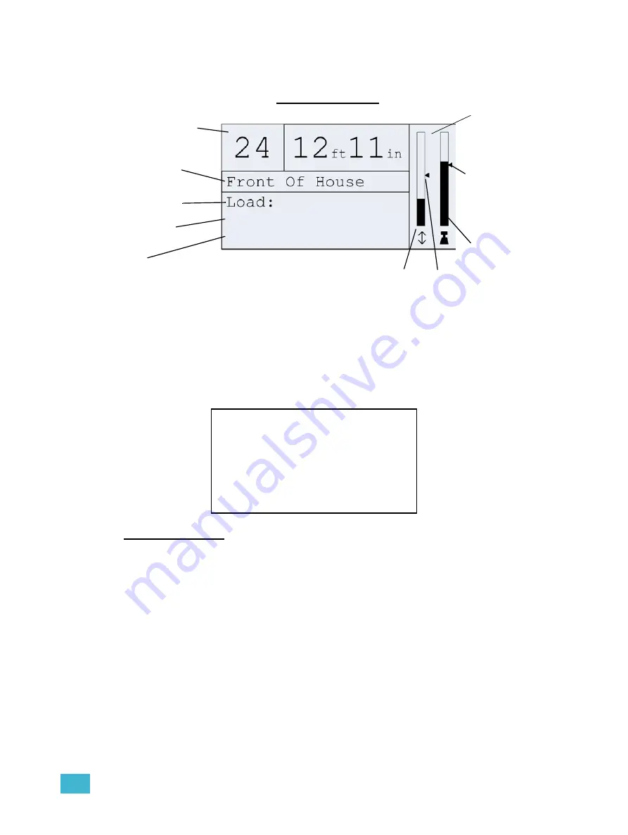
When a motor is selected, the motor status screen offers important information about it. The
various components of the status screen are identified below.
System Not OK
The “System Not OK” screen is displayed, alternating with the contact information screen, and
the related motor select button(s) will flash red. Press the flashing red motor select button and
the errors will be displayed on the bottom two lines. If more than two errors exist, they will scroll
on the bottom two lines. Look for the motor select button or buttons with a flashing red LED
indicating the error.
Motor Select LEDs
The motor select buttons are equipped with LEDs to signify various conditions using a range of
color indicators.
The definitions for the various color states for the motor select buttons are:
White -
motor selected, but not moving
Blinking Blue -
motor moving up
Blinking Green -
motor moving down
Blinking White -
trim being recorded
Alternating Red and other
-
Error (see
Alternating Yellow and other
- Informational messages
LED Dim -
motor not selected
LED Off
- inactive button/no motor assigned
Motor number
Trim 2:
Speed:
300 lb
16’9”
90 fpm
Motor name
Current load
Current trim
height
Speed
(Status messages will be
shown here when active)
Bar graph of
current position
in travel range
Location of
current trim in
travel range
Bar graph of
current load in
load range
Recorded load
marker
Motor Status Screen
Location of
High Trim
Qui 24
Qui 24
Rigging Controller
Rigging Controller
System NOT OK
System NOT OK
Check Hoist X
Check Hoist X
Summary of Contents for QuickTouch+ 12
Page 10: ...6 QuickTouch Control Station User Manual...
Page 18: ...14 QuickTouch Control Station User Manual...
Page 31: ......


