background image


43 

Retrieving and input of calibration value


1. Connect APH550 and the PC. 
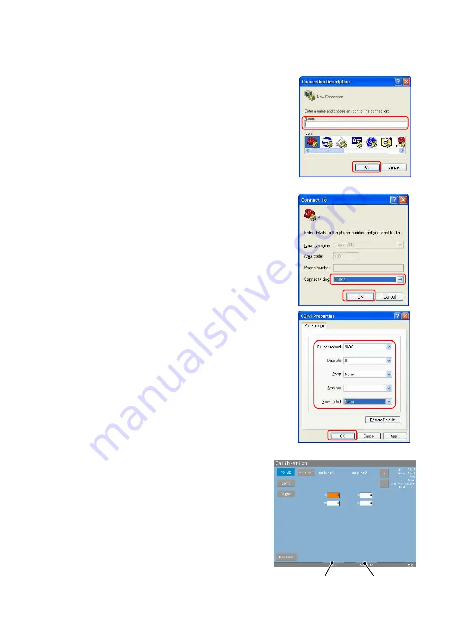
2. Start up the hyper terminal and match the 

setting of the PC with the one of APH550.     

  ※

The setting procedures of the hyper terminal. 

    ①

Start up the hyper terminal of PC, input   


the setting name in “Name” and press “OK”. 


    ②

Select the port which connects the cable   


from “Connect using” and press “OK”. 


    ③

Set the details of “Port Settings” same   


with the ones of APH550 and press “OK”. 


Setting of APH550 


Bits per second  :9600 or 115200 


Data bits 

:8 


Parity   

:None 


Stop bits 

:1 


Flow control 

:None 


3. Press the “Output PC button”.   

The data is output to the PC. 

4. Save the output data as the text data.   
5. Overwrite and save it after matching the 

saved data values with the values for the 
repair parts.     


Output PC button 

Import button 

Summary of Contents for APH 550

Page 1: ...Automatic Phoropter Maintenance Manual V1 09 2016...

Page 2: ...l Diagram 1 2 Block Diagram 6 3 Connection Diagram 7 4 Wiring Diagram 9 5 Troubleshooting 12 6 Cleaning of Measuring Windows 40 7 Maintenance Mode 41 8 Replacement procedure of each unit 50 9 Rewritin...

Page 3: ...assy 6 Head rest adjustment knob assy 11 Measuring window 2 2 Face shield R assy 7 Near point chart fixing knob 12 Measuring window 3 3 Face shield L assy 8 Joint fixing knob assy 13 VD check windows...

Page 4: ...ication board assy 12 Leveling adjustment knob assy 3 Right side motor drive board assy 7 LD R assy 13 Chart stopper 4 Left side motor drive board assy 8 LD L assy 14 Head unit peripheral harness 5 LE...

Page 5: ...l structural diagram controller No Name 1 LCD case 1 assy 2 LCD case 2 3 Operation unit case assy 4 Body case 1 5 Body case 2 6 Printer cover 7 Open switch 8 Operation dial assy 9 LCD panel assy 9 1 8...

Page 6: ...4 1 4 Internal structural diagram controller No Name 1 Control board assy 2 Operation board assy 3 Printer control board assy 4 Relay board assy 5 Printer case 6 LCD panel assy 7 Thermal printer...

Page 7: ...5 1 5 External structural diagram relay box 1 6 Internal structural diagram relay box No Name 1 Power case 2 Power switch No Name 1 Communication board assy 2 Switching power supply assy 1 2...

Page 8: ...or control circuit Position detecting sensor Head unit Interface Enclosure Power supply box unit Fuse Power switch Communication control circuit Basic insulation Switching supply Reinforced insulation...

Page 9: ...7 3 Connection Diagram...

Page 10: ...8...

Page 11: ...rness Motor drive unit harness Sensor relay harness Right motor drive board assy Position detecting sensor harness VD L assy LED harness for lighting eyeball LED board assy for lighting left eyeball L...

Page 12: ...tion board assy Operation harness Control printer harness Printer case Thermal printer Printer flame harness Flame harness Control printer harness Printer control board assy Relay board assy Thermal p...

Page 13: ...11 4 3 Relay box Communication board assy SWPS output harness Switching power supply assy Inlet earth harness SWPS input harness Power supply SW harness Earth harness 2 SWPS output harness...

Page 14: ...message Right Lens 6 In Error or Left Lens 6 In Error appears 5 12 Error message Right Lens 6 Out Error or Left Lens 6 Out Error appears 5 13 Error message Error 7 appears 5 14 Error message Error 8 a...

Page 15: ...is in the process of the program rewriting of the control board The functions of the main boards are shown below 1 Control board assy LCD control touch panel control 2 Operation board assy Operation s...

Page 16: ...le Is the display of the LCD switched depending on the operation of the controller Go to NO if nothing is displayed on the LCD YES NO Connect the connector for the controller of the relay box and the...

Page 17: ...Connect the connector for connecting the LD L assy of the motor control board assy CN103 and CN302 of the right motor drive board assy and the connector for connecting the LD R assy of the motor cont...

Page 18: ...ses when error message Printer Overheated appears Failure of thermal printer Failure of printer control board assy Printer Overheated appears Replace the thermal printer Replace the printer control bo...

Page 19: ...pears No printer papers in printer Failure of thermal printer Failure of printer control board assy Paper Empty appears Does Paper Empty still appear Replace the printer control board assy OK Are the...

Page 20: ...paper is stuck in cutter portion Failure of thermal printer Failure of printer control board assy Are the printer papers stuck in the printer portion YES NO Printer Cutter Error appears YES OK Does P...

Page 21: ...he device can be used without replacing the PD assy In such case however use the device after confirming that the error does not appear anymore by pressing the clear key and performing the initial ope...

Page 22: ...he device can be used without replacing the PD assy In such case however use the device after confirming that the error does not appear anymore by pressing the clear key and performing the initial ope...

Page 23: ...device can be used without replacing the LD R assy or the LD L assy In such case however use the device after confirming that the error does not appear anymore by pressing the clear key and performin...

Page 24: ...can be used without replacing the LD R assy or the LD L assy In such case however use the device after confirming that the error does not appear anymore by pressing the clear key and performing the in...

Page 25: ...can be used without replacing the LD R assy or the LD L assy In such case however use the device after confirming that the error does not appear anymore by pressing the clear key and performing the i...

Page 26: ...ce can be used without replacing the LD R assy or the LD L assy In such case however use the device after confirming that the error does not appear anymore by pressing the clear key and performing the...

Page 27: ...25 5 13 Error message Error7 appears Main causes when error message Error7 appears Failure of control board assy Error7 appears OK Replace the control board assy...

Page 28: ...26 5 14 Error message Error8 appears Main causes when error message Error8 appears Failure of control board assy Error8 appears OK Replace the control board assy...

Page 29: ...utlet Refer to 5 23 Nothing is displayed on the screen Is the power indicator of the controller turned on Replace the relay board assy NO YES Is the communication cable normal YES Replace the communic...

Page 30: ...oard assy Are the printer harness and the control printer harness normal YES NO Is the screen display normal NO Does the head move or it beep when operating the device with the operation switches or t...

Page 31: ...e of operation board assy Failure of relay board assy Failure of operation harness Replace the operation board assy OK Is the performance of the switches normal Replace the relay board assy YES Is the...

Page 32: ...ssy Failure of LCD panel assy Replace the LCD panel assy The touch panel does not work OK Is the performance of the touch panel normal Does it work when operating it with the operation switches or the...

Page 33: ...rintout is not normal Failure of thermal printer Failure of printer control board assy Failure of control board assy Replace the control board assy Replace the printer control board assy YES NO OK No...

Page 34: ...ness of the LED for lighting the eyeball normal NO Interchange between the LED board assy for lighting the right eyeball and the LED board assy for lighting the left eyeball and connect them Replace t...

Page 35: ...the harness of the LED for lighting the eyeball Does the LED for lighting the eyeball light up NO Does the LED for lighting the eyeball light up NO YES Replace the LED board assy for lighting the eye...

Page 36: ...e LED for lighting the near chart does not light up YES Replace the motor control board assy OK NO Replace the control board assy Does the LED for lighting the near point chart light up Are the periph...

Page 37: ...place the control board assy Are the type of the chart and the setting of the channel correct NO YES Correct the setting Refer to 7 2 4 Replace the infrared communication board assy OK Is the infrared...

Page 38: ...rent Failure of communication board assy Failure of control board assy Cannot communicate with the autoref lensmeter or PC Replace the communication board assy Can it communicate with the autoref lens...

Page 39: ...use blown out Note Make sure to plug out after checking YES Replace the fuse NO YES Does the power indicator of the relay box light up Pug out the communication cable which connects the controller and...

Page 40: ...ctors which are connected to the board to be checked 2 Check if it is shorted out or not between 2 pins based on the table below Board to be checked 2 pins to be checked Board of controller Control bo...

Page 41: ...board assy and operation board assy Error 10 Abnormal communication between control board assy and printer board assy Error 11 Abnormal communication between control board assy and motor control boar...

Page 42: ...the test results if they have fingerprints or dust etc on 1 Saturate K dry cleaning material or soft cloth with the neutral detergent 2 Clean the measuring windows in a circular motion Repeat it until...

Page 43: ...n on the right appears by pressing and holding the dial push key 3 The maintenance mode is started up approximately 5 seconds after of displaying Maintenance Mode Loading The menu screen appears when...

Page 44: ...lue and exit the mode Changing procedures of setting value 1 First touch the button which to be changed PD WD button Left button or Right button 2 Next select the Adjust area of the setting value to b...

Page 45: ...K Select the port which connects the cable from Connect using and press OK Set the details of Port Settings same with the ones of APH550 and press OK Setting of APH550 Bits per second 9600 or 115200 D...

Page 46: ...t Select the file saved on the procedure 5and press Open 7 Press the Import button after sending 7 2 2 Adjust data output Print out the adjustment data by touching this button Also the version informa...

Page 47: ...tance of 60cm 70 Set the near point chart at the distance of 70cm Disk drive motor Select the disk to be driven with the Disk selection button After that the disk starts driving by touching the Disk d...

Page 48: ...cks the performance of the LED PD Switch ON OFF of LED for lighting eyeball Near point Switch ON OFF of LED for lighting near point chart 3 Touch panel Check The screen on the right appears by selecti...

Page 49: ...dial switch Failure of the operation board assy etc might be the cause when ON is not displayed even though pressing each button or ON is displayed even though no buttons are pressed 5 Printer Check...

Page 50: ...th the one of the chart Chart model Set the type of chart Chart ch Set the channel of chart 2 Motor Speed Do not change the setting value because it is fixed 3 Model Select Switch the autoref or lensm...

Page 51: ...settings of each item 7 3 Calibration of touch panel This device has the mode to calibrate the touch panel Make sure to follow the procedures below after replacing the LCD panel assy etc 1 Turn the po...

Page 52: ...ing left eyeball LED harness for lighting the eyeball and sensor relay harness 8 1 5 Replacement of LD R assy and LD L assy 8 1 6 Replacement of PD assy 8 1 7 Replacement of joint block assy leveling...

Page 53: ...replacing the board harness Also do not squeeze the harness at the time of assembling 2 Apply screw lock after tightening it when screwing at where screw lock was originally applied 3 Check the opera...

Page 54: ...case of removing the right LD case F unscrew 2 screws for fixing the case inside of the Face shields after removing the head rest and the Face shields 4 The right LD case F is fixed with one internal...

Page 55: ...g the power on refer to PD input of 5 4 Basic Operation of the Operation Manual 8 Tilt the near point chart holder horizontally after removing the near point chart fixing knob assy and the Head rest a...

Page 56: ...screws for fixing the case 10 Procedure of disassembling is finished Reassemble it with the opposite procedures of disassembling Do not squeeze the harness with the case at the time of assembling Scre...

Page 57: ...nit harness and position detecting sensor harness 1 Remove the PD case F and the right LD case F and B refer to 8 1 1 2 Replace the right side motor drive board assy after removing 3 screws for fixing...

Page 58: ...the plate when unscrewing the 2 board fixing screws 1 3 Remove and replace all of the harnesses connected to 2 board fixing screws 2 at the time of replacing the LED board assy for lighting the right...

Page 59: ...ll Push the board in as the arrow shown on the right below when placing the board 3 Replace the LED board assy for lighting the right eyeball by pulling it out from the VD R assy after removing the VD...

Page 60: ...confirm that the head is horizontal by the level and adjust and fix it as its standard face to be horizontal Also fix it as the boss for positioning the LD R assy and the hole for positioning the PD a...

Page 61: ...D case B refer to 8 1 1 3 Remove the LD R assy LD L assy and the motor drive unit harness refer to 8 1 5 4 Replace the PD assy after removing it from the measuring table etc 5 Input the data changed o...

Page 62: ...e chart stopper and unscrewing 2 fixing screws 4 Remove the joint block assy by removing the Leveling adjustment knob assy and the Leveling adjustment spring post first and then removing the E ring ei...

Page 63: ...astic adhesive Remove the left LD case F by rotating it in a clockwise direction 3 Remove the VD check window after unscrewing 2 fixing screws 4 Remove the right LD case B refer to 8 1 1 5 Replace the...

Page 64: ...e 2 and insert the flat blade screwdriver in it 4 Displace the LCD assy to the back and the LCD case 2 to the front with one hand and turn the flat blade screwdriver and unfix the tabs with the other...

Page 65: ...CD panel assy after removing 4 fixing screws LCD harness and touch panel harness 10 Procedure of disassembling is finished Reassemble it with the opposite procedures of disassembling Calibrate the tou...

Page 66: ...crew 4 fixing screws and remove the body case 1 4 Replace the open switch after unscrewing the fixing screw on the back of the body case 1 5 Remove the LCD case 2 after unscrewing 4 hinge fixing screw...

Page 67: ...er unscrewing 3 fixing screws and removing the earth harness 11 Replace the printer case after removing the thermal printer and the printer control board assy Hinge fixing screws Fixing screws 1 LCD c...

Page 68: ...nit after unscrewing 2 fixing screws Reassemble it as the roller unit to be parallel to the case 15 Replace the relay board assy after unscrewing 4 board fixing screws and removing all of the harnesse...

Page 69: ...ing the operation dial assy The operation dial assy and the operation board assy are fixed with 4 tabs The tabs are placed at where 4 ribs are not placed Insert the small flat blade screwdriver in the...

Page 70: ...the operation button 6 Procedure of disassembling is finished Reassemble it with the opposite procedures of disassembling At the time of reassembling of the operation board assy place the operation d...

Page 71: ...munication board assy after unscrewing 5 board fixing screws and removing all of the harnesses connected to the communication board assy 3 Replace the switching power supply assy and the harness after...

Page 72: ...efer to 8 3 1 2 Remove all of the harnesses connected to the power supply switch 3 Pinch A parts with a nipper etc and press it out to B direction 4 Place the new power supply switch in the main unit...

Page 73: ...ment of fuse 1 Replace the fuse by holding 2 tabs as shown below and taking it out 2 Reassemble it with the opposite procedures of disassembling Brown Light blue To fuse holder To fuse holder Light bl...

Page 74: ...72 8 3 4 Replacement of leg of relay box 1 Turn the unit over 2 Replace 4 fixing screws Fixing screw Leg of relay box...

Page 75: ...setting of the application Set the communication port and communication speed of the application of software rewriting Set the communication port depending on the PC environment Set the Product mode...

Page 76: ...the program file to rewrite 4 Connection of APH550 and PC Connect the RS 232C cable with the relay box of APH550 and PC 5 Switch APH550 to the mode of program rewriting Turn the power on with pressin...

Page 77: ...The setting of the Hyper mode Enter the Hyper mode by pressing the right button It is cancelled by pressing the left button Press the XC1 button after setting the communication Please Send MOT File i...

Page 78: ...76...

Reviews: