Remote IP Feature Phone Installation Manual
Connecting the Remote IP Feature Phone
E.1
Connecting the
Remote IP Feature Phone
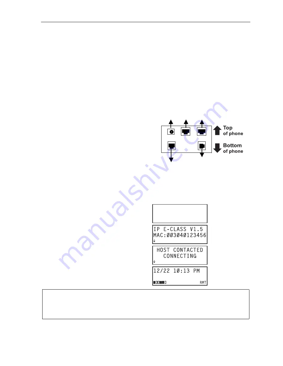
Connect the Remote IP Feature Phone directly, or through a hub or switch, to modem or NAT router. At
this point, installation of the Remote IP Feature Phone is similar to that for the IP Local Phone.
1.
Use the provided RJ-45 Cat-5 cable to connect from the connector marked
NETWORK
to the
device (router or DSL or cable modem).
2.
If a PC workstation is to be connected through the phone, use a RJ-45 Cat-5 cable to connect
directly from the phone connector marked
PC
to the RJ-45 connector on the back of the PC.
If a PC is connected to the phone, the PC should be powered up prior to applying power to
the phone.
3.
If a 60-Key Expansion Console is being installed with
the Remote IP Feature Phone, use the provided
expansion cable to connect between the phone’s
expansion connector (
“To 60-Key Console”
in
artwork,
right
) and the connector on the console.
No other connection is needed. The console draws
its power from the IP Phone’s power supply through
the cable.
4.
Connect the handset cord into the phone connector
marked
HANDSET
.
5.
Connect the power supply module to the Remote IP
Feature Phone.
At this point the Remote IP Feature Phone will power-up and attempt to make connection to the main
office IP PBX. The successful power sequence will be as follows:
Blank display for several seconds
Power-up display
Contacting remote host
Normal Remote Phone display
(with six RNC channels enabled)
Note:
The arrows that briefly appear on the display during connection mean:
Ï
— Not connecting to remote system.
Ð
— Reconnecting to remote system.
To 60-Key
Console
Handset
To power
supply
To
PC
To
LAN


