


17
CO
2
Incubator
3.3.2 Analog Output Calibration (
for units with optional analog output
)
A set of relay contacts are provided at the rear of the incubator that allows that allow the incubator to output
analog signals representing the temperature, %CO2, %O2 (for suppressed O
2
model) and %RH depending on
the options available in your incubator. This allows the chamber to be connected to an in-house data
acquisition or alarm system.
The analog data output can be set to operate in either DC (0-5 V) or current (4-20 mA) mode. The factory
default setting is voltage. The voltage of the analog output can be calibrated using a calibrated digital multi
meter.
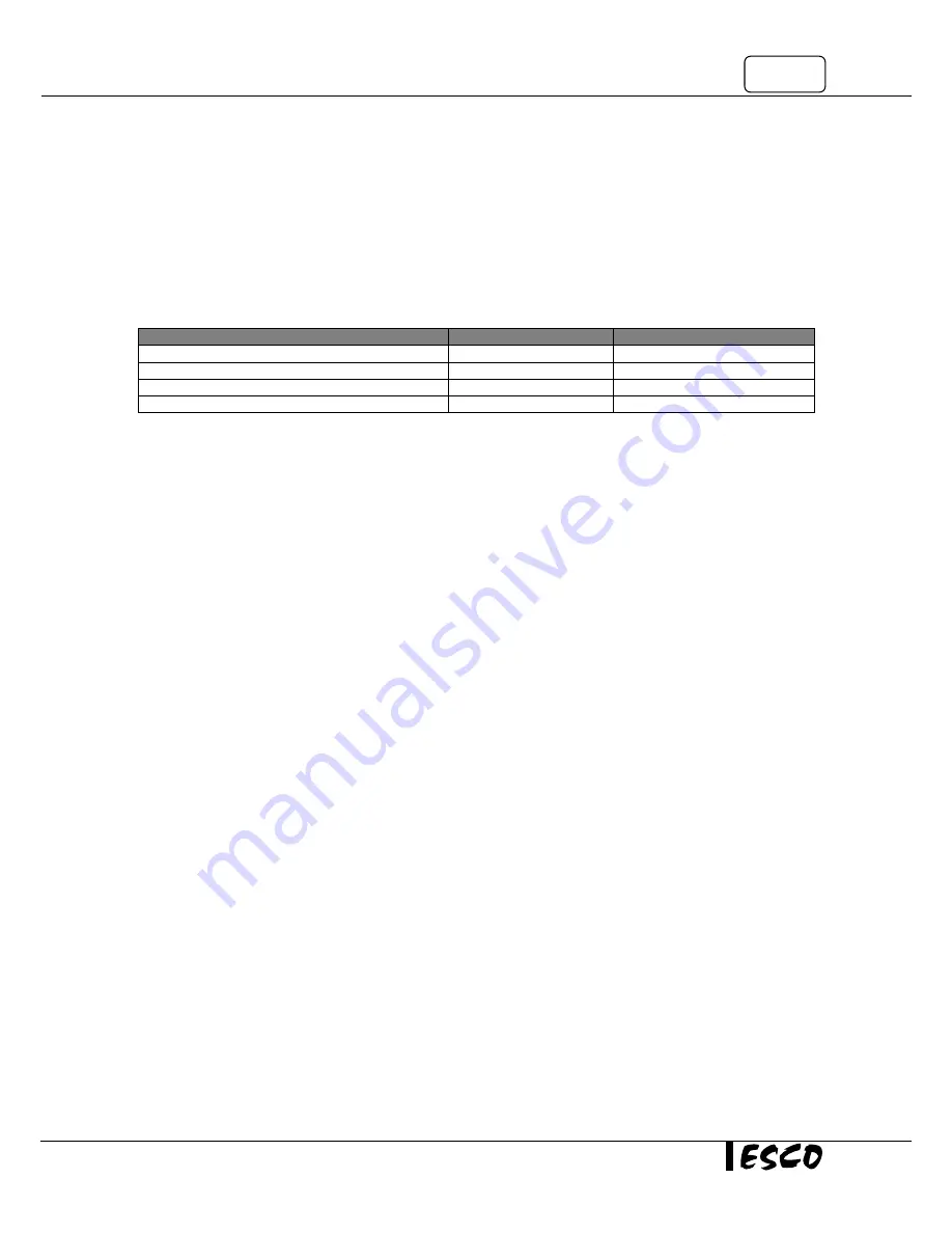
To calibrate
Rear Panel Terminal
MENU | SERVICE
Temperature Analog Output
Temp (+ and -)
Calibrate A/O Temp
CO2 Analog Output
CO2 (+ and -)
Calibrate A/O CO2
% Relative Humidity Analog Output
RH (+ and -)
Calibrate A/O RH
O2 Temperature Analog Output
O2 (+ and -)
Calibrate A/O O2
Place the multi meter’s measuring probe on the resp and - terminals of the analog output located at
the rear panel and record the measured value.
Enter MENU|SERVICE and select the responding options. When asked, enter the measured value. Press SET to
confirm.
Summary of Contents for CelCulture CO2
Page 8: ...CelCulture vi...
Page 10: ...CelCulture viii...
Page 14: ...CelCulture 4...
Page 20: ...CelCulture 10...
Page 30: ...CelCulture 20...
Page 38: ...CelCulture 28...
Page 39: ...APPENDIX...
Page 40: ......
Page 42: ......