background image

12

Operation

Before installing any components, follow the safety information in the ETS-Lindgren 

Product 

Information Bulletin

 included with your shipment.

2301 Precision Positioner Command Set

Ensure the current travel limit settings will not cause damage to existing cables.
 
Do not operate the 2301 Precision Positioner in a stalled condition. Doing so can cause 
damage to the drive unit and will void the warranty. Ensure the positioner will continue to rotate 
under load at all speeds.

General Command Structure

Most of the following commands use this general structure:

[SUBSET:]AXIS<n[-m]>:COMMAND <argument_n>[,<argument_m>]

Where:

[ ] 

Indicates optional.

< >

Indicates required.

COMMAND

The backwards compatible Model 2090 Multi Device Controller command.

When used by itself, controls the first device in a multi axis system, and, when 

arguments are required, supports only a single argument.

The command prefix in 

optional brackets [ ]

Required to access a specific axis or multiple axes at a time.

SUBSET

The particular command grouping subset (e.g. configure, control, etc.).

AXIS<n[-m]>

Selects the desired axis or axes to control.

A single index specifies a single axis (e.g. AXIS1 or AXIS2) with a single argument, 

while a range (e.g. AXIS1-2) specifies a range of axes with a corresponding range 

of arguments.
Note that some commands only support single axis control.

<argument_n>

The single argument required for a single axis command.

[,<argument_m>]

Represents the additional arguments required for an optional multi axis command

(e.g. SUBSET:AXIS1-2:COMMAND 1,2).

Summary of Contents for ETS-LINDGREN 2301

Page 1: ...2301 Positioner User Manual 1723531 Rev B January 2021...

Page 2: ...does it convey any license under its patent rights nor the rights of others All trademarks are the property of their respective owners Copyright 2020 2021 by ETS Lindgren Inc All Rights Reserved No p...

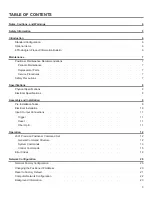
Page 3: ...ons 8 Physical Specifications 8 Electrical Specifications 8 Assembly and Installation 9 Pre Installation Tasks 9 Electrical Installation 10 Input Output Connections 11 Trigger 11 Reset 11 Fiber Optic...

Page 4: ...uct Caution Denotes a hazard Failure to follow instructions could result in minor personal injury and or property damage Included text gives proper procedures Warning Denotes a hazard Failure to follo...

Page 5: ...ive grounding conductor inside or outside the instrument or disconnection of the protective earth terminal could result in personal injury Warning HEAVY OBJECT Unassisted lifting can cause injury Mech...

Page 6: ...an illuminated switch and the inlet for the customer s EUT is operated by a non illuminated switch Labels on the top surface of the motor base indicate the location of each inlet Standard Configuratio...

Page 7: ...heck cables for wear Ensure they are clear of potential damage from moving parts Ensure bearing and pinion have adequate lubrication Replacement Parts Following are the part numbers for ordering repla...

Page 8: ...out Base Station Mount 167 64 cm 66 0 in Height with Base Station Mount 213 11 cm 83 9 in Width 103 63 cm 40 8 in Depth 101 60 cm 40 0 in Overall Weight 90 72 kg 200 0 lb Maximum Load Capacity 24 95 k...

Page 9: ...for aligning system Customer provides RF power and control cabling to the top of the unit and to the EUT 2 The center of rotation for the unit must intersect the line through the bore sight of the mea...

Page 10: ...power source is appropriate for the wire gauge used and that the wire gauge is adequate for the motor load Using undersized wire gauge will result in a higher than expected voltage drop in the power...

Page 11: ...0 Used in case the IP address of the device is unknown Fiber Optic The positioner is equipped with a fiber optic inlet and a fiber optic outlet Connect the positioner to the included Ethernet to fiber...

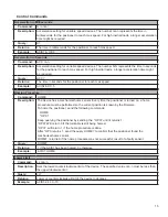
Page 12: ...d COMMAND The backwards compatible Model 2090 Multi Device Controller command When used by itself controls the first device in a multi axis system and when arguments are required supports only a singl...

Page 13: ...TS Lindgren Inc 2301 Precision Positioner Module Name PCA120518 FW N NN identifies this device as a 2301 Precision Positioner The Module Name parameter is a place holder to identify a specific module...

Page 14: ...e Name parameter in the IDN query response is a place holder to identify a specific device in a network If you have more than one device you might want to identify them with different module names For...

Page 15: ...e Command HOME Description The device has a mechanical home sensor Every time the positioner is turned on a home procedure must be performed so the current position is known by the firmware To home th...

Page 16: ...pleted See Homing Procedure p 14 Example AXIS1 OPC Scan Command SCAN Description Instructs the positioner to begin scanning between preset lower and upper limits Example AXIS1 SCAN Seek Negative Comma...

Page 17: ...nd lower counterclockwise limits Example AXIS2 SKP 90 Seek Relative Command SKR nnn n Description Instructs the device to begin seeking the specified target value relative to the current position The...

Page 18: ...ample AXIS1 2 ST Trigger Configuration Command TRIGGER ON OFF step size reference pre trigger delay pulse length post trigger delay polarity Description Use this command to configure the trigger Where...

Page 19: ...rection 5 Hardware Limit hit 6 Polarization limit violation 7 Lost communication 9 Encoder failure 10 Trigger failure 11 Motor overheat 12 Relay failure 13 Position out of bounds 32 Motor driver fault...

Page 20: ...using the same IP address The IP address of the device will need to be changed if more than one device is in the same LAN To change the IP address of an ETS Lindgren Ethernet device use its embedded...

Page 21: ...e the connection is working by typing IDN then pressing the Enter key on the keyboard The device will respond with an identification string such as the one shown below The IP address can be changed us...

Page 22: ...22 Computer Network Configuration Connect to an ETS Lindgren Ethernet by setting the computer Ethernet interface to the selections shown below...

Page 23: ...net cables It also communicates with the computer and allows it to access a network device Follow these steps on a Windows 10 PC to configure the Ethernet adapter 1 Ensure that the Ethernet adapter is...

Page 24: ...ange Ethernet settings In the search results click change Ethernet settings In the Settings window click Change adapter options Right click on the Ethernet Adapter you intend to configure and select P...

Page 25: ...192 168 0 1 Subnet mask 255 255 255 0 Default gateway blank Select Use the following DNS server addresses and leave Preferred and Alternate DNS server fields blank Then click OK Information about subn...

Page 26: ......

Reviews: