561
section 5
maintenance
5.3
iGBt handling
5.4
module Replacement
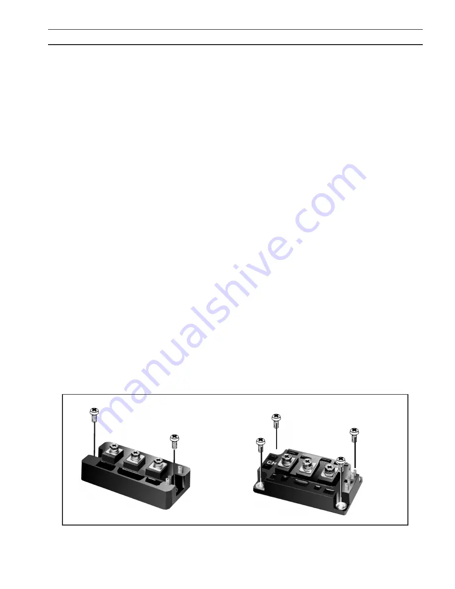
Two-Point Mounting Type
Initial tightening
Final tightening
Four-Point Mounting Type
Initial tightening
Final tightening
Since IGBT gates are insulated from any other conducting region, care should be taken to prevent static build up, which
could possibly damage gate oxides. All IGBT modules are shipped from the factory with conductive foam contacting the
gate and emitter sense pins.
Always ground parts touching gate pins during installation. In general, standard ESD precautions application to FETs should
be followed.
Other handling precautions that should also be observed are as follows:
•
Use grounded work station with grounded floors and grounded wrist straps when handling devices.
•
Use a 100
Ω
resistor in series with the gate when performing curve tracer tests.
•
Never install devices into systems with power connected to the system.
When mounting modules on a heatsink, certain precautions should be taken to prevent any damage against a sudden
torque. If a sudden torque (“one-sided tightening”) is applied at only one mounting terminal the ceramic insulation plate
or silicon chip inside the module may get damaged.
The mounting screws are to be fastened in the order shown in Figure 5-1. Also, care must be taken to achieve maximum
contact (i.e. minimum contact thermal resistance) for the best heat dissipation.
A torque wrench should be used. Tighten mounting and terminal screws per Torque Requirements shown in Subsection 7.3.
If device is over-torqued, the device can be damaged like the above “one-sided tightening”.
Application of a Thermal Compound or Thermal Pad on the contact surface is required to properly remove heat from the
device. It is recommended that a unit manufactured with thermal compound use thermal compound for replacement, even
if replacement module was shipped with a thermal pad. Thermal compound may always be used as a replacement for a
pad. Never use both compound and a pad.
Thoroughly remove any residual material from the mating surfaces. Use Dow-340 Heat Sink Compound or equivalent. Apply
a thin layer (.005” nominal) between mating surfaces. If a thermal pad is used, ensure there are no folds or creases.
figure 5-1 screw fastening order
Summary of Contents for Powercut-1600
Page 4: ...4 table of contents ...
Page 11: ...11 MANUEL PLASMARC SKÆREENHED Powercut 1300 1600 ...
Page 12: ...12 ...
Page 24: ...24 SEKTION 3 INSTALLATION ...
Page 32: ...32 SEKTION 4 BETJENING ...
Page 33: ...33 MEKANISERET PLASMARC SKÆREENHED Powercut 1300 1600 ...
Page 34: ...34 ...
Page 57: ...57 HANDMATIG PLASMARC SNIJPAKKET Powercut 1300 1600 ...
Page 58: ...58 ...
Page 70: ...70 HOOFDSTUK 3 INSTALLATIE ...
Page 78: ...78 HOOFDSTUK 4 BEDIENING ...
Page 79: ...79 MACHINAAL PLASMARC SNIJPAKKET Powercut 1300 1600 ...
Page 80: ...80 ...
Page 103: ...103 MANUAL PLASMARC CUTTING PACKAGE Powercut 1300 1600 ...
Page 104: ...104 ...
Page 116: ...116 SECTION 3 INSTALLATION ...
Page 124: ...124 section 4 operation ...
Page 125: ...125 MECHANIZED PLASMARC CUTTING PACKAGE Powercut 1300 1600 ...
Page 126: ...126 ...
Page 149: ...149 MANUAALINEN PLASMARC LEIKKAUSJÄRJESTELMÄ Powercut 1300 1600 ...
Page 150: ...150 ...
Page 162: ...162 OSA 3 ASENNUS ...
Page 170: ...170 OSA 4 KÄYTTÖ ...
Page 171: ...171 MEKAANINEN PLASMARC LEIKKAUSJÄRJESTELMÄ Powercut 1300 1600 ...
Page 172: ...172 ...
Page 195: ...195 ENSEMBLE DE COUPAGE MANUEL À L ARC PLASMA Powercut 1300 1600 ...
Page 196: ...196 ...
Page 208: ...208 SECTION 3 INSTALLATION ...
Page 216: ...216 section 4 FONCTIONNEMENT ...
Page 217: ...217 ENSEMBLE DE COUPAGE À L ARC PLASMA AUTOMATIQUE Powercut 1300 1600 ...
Page 218: ...218 ...
Page 241: ...241 PLASMARC SCHNEIDAUSRÜSTUNG FÜR MANUELLES PLASMASCHNEIDEN Powercut 1300 1600 ...
Page 242: ...242 ...
Page 254: ...254 ABSCHNITT 3 INSTALLATION ...
Page 262: ...262 ABSCHNITT 4 BETRIEB ...
Page 263: ...263 PLASMARC SCHNEIDAUSRÜSTUNG FÜR MECHANISIERTES PLASMASCHNEIDEN Powercut 1300 1600 ...
Page 264: ...264 ...
Page 287: ...287 PACCHETTO DI TAGLIO PLASMARC MANUALE Powercut 1300 1600 ...
Page 288: ...288 ...
Page 300: ...300 SEZIONE 3 INSTALLAZIONE ...
Page 308: ...308 SEZIONE 4 FUNZIONAMENTO ...
Page 309: ...309 PACCHETTO DI TAGLIO PLASMARC MECCANIZZATO Powercut 1300 1600 ...
Page 310: ...310 ...
Page 333: ...333 MANUELL PLASMARC SKJÆREPAKKE Powercut 1300 1600 ...
Page 334: ...334 ...
Page 346: ...346 KAPITTEL 3 INSTALLASJON ...
Page 354: ...354 KAPITTEL 4 BRUK ...
Page 355: ...355 MEKANISERT PLASMARC SKJÆREPAKKE Powercut 1300 1600 ...
Page 356: ...356 ...
Page 379: ...379 ZESTAW DO RĘCZNEGO CIĘCIA ŁUKIEM PLAZMOWYM Powercut 1300 1600 ...
Page 380: ...380 ...
Page 392: ...392 ROZDZIAŁ 3 INSTALACJA ...
Page 400: ...400 ROZDZIAŁ 4 EKSPLOATACJA ...
Page 401: ...401 ZESTAW DO ZMECHANIZOWANEGO CIĘCIA ŁUKIEM PLAZMOWYM Powercut 1300 1600 ...
Page 402: ...402 ...
Page 425: ...425 CONJUNTO DE CORTE DE ARCO DE PLASMA MANUAL Powercut 1300 1600 ...
Page 426: ...426 ...
Page 438: ...438 CAPÍTULO 3 INSTALAÇÃO ...
Page 446: ...446 CAPÍTULO 4 FUNCIONAMENTO ...
Page 447: ...447 CONJUNTO DE CORTE DE ARCO DE PLASMA MECANIZADO Powercut 1300 1600 ...
Page 448: ...448 ...
Page 471: ...471 PAQUETE DE CORTE PLASMARC MANUAL Powercut 1300 1600 ...
Page 472: ...472 ...
Page 484: ...484 APARTADO 3 INSTALACIÓN ...
Page 492: ...492 APARTADO 4 FUNCIONAMIENTO ...
Page 493: ...493 PAQUETE DE CORTE PLASMARC MECANIZADO Powercut 1300 1600 ...
Page 494: ...494 ...
Page 517: ...517 MANUELLT PLASMARC SKÄRPAKET Powercut 1300 1600 ...
Page 518: ...518 ...
Page 530: ...530 AVSNITT 3 INSTALLATION ...
Page 538: ...538 AVSNITT 4 ANVÄNDNING ...
Page 539: ...539 MEKANISERAT PLASMARC SKÄRPAKET Powercut 1300 1600 ...
Page 540: ...540 ...
Page 557: ...557 Powercut 1300 1600 MAINTENANCE TROUBLESHOOTING SCHEMATIC DIAGRAMS REPLACEMENT PARTS ...
Page 558: ...558 ...
Page 562: ...562 section 5 maintenance ...


