120
4.2
Cutting with the Powercut-1300/1600 using the PT-38 torch
Use the following procedures to cut with the PT-38 torch.
A.
Make sure that the wall disconnect switch is on and air is supplied to machine.
B.
Turn on the front panel power switch.
C.
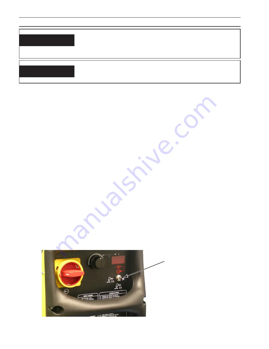
Flip toggle switch upward to place unit in "GAS TEST" mode. Set Pressure Regulator to 80 psig (5.5 bar).
D. Place unit in Normal Trigger (CENTER position) or Trigger Lock (DOWN position).
E.
Hold the torch nozzle approximately 1/8 - 1/4 inch (3.2 - 6.4 mm) above the work and tilted at about 5 -15°. This reduces
the chance of spatter entering the nozzle. If the PT-38's 90A stand-off guide is being used, the distance between nozzle
and work piece will be approximately 1/4" (6.4 mm).
F.
Depress the torch switch. Air should flow from the torch nozzle.
G. Two seconds after depressing the torch switch, the pilot arc should start. The main arc should immediately follow,
allowing the cut to begin. (If using the TRIGGER LOCK feature, torch switch may be released after establishing the
cutting arc.) See note.
NOTE: Trigger Lock Mode.
Manual Operation using the PT-38 torch
- When placed in TRIGGER LOCK position, this permits re-
leasing torch switch button after cutting arc has been initiated. To extinguish arc at end of cut, press
and release torch switch button again or pull torch away from work. When placed in NORMAL TRIGGER
position, torch switch must be held closed by the operator during the entire cutting operation and then
released at the end of cut.
Torch Trigger / Gas Test Switch
SECTION 4
OPErATION
POSITION THE POWErCUT AT LEAST 10 fEET (3 METErS) frOM THE
CUTTINg ArEA. SPArKS AND HOT SLAg frOM THE CUTTINg OPErA-
TION CAN DAMAgE THE UNIT.
WArNINg
WArNINg
ArC rAYS CAN BUrN EYES AND SKIN;
NOISE CAN DAMAgE HEArINg.
• wear welDiNg helmeT wiTh No. 6 or 7 leNs shaDe.
• wear eye, ear, aND boDy proTecTioN.
figure 4-3. Torch Trigger / gas Test Switch
Summary of Contents for Powercut-1600
Page 4: ...4 table of contents ...
Page 11: ...11 MANUEL PLASMARC SKÆREENHED Powercut 1300 1600 ...
Page 12: ...12 ...
Page 24: ...24 SEKTION 3 INSTALLATION ...
Page 32: ...32 SEKTION 4 BETJENING ...
Page 33: ...33 MEKANISERET PLASMARC SKÆREENHED Powercut 1300 1600 ...
Page 34: ...34 ...
Page 57: ...57 HANDMATIG PLASMARC SNIJPAKKET Powercut 1300 1600 ...
Page 58: ...58 ...
Page 70: ...70 HOOFDSTUK 3 INSTALLATIE ...
Page 78: ...78 HOOFDSTUK 4 BEDIENING ...
Page 79: ...79 MACHINAAL PLASMARC SNIJPAKKET Powercut 1300 1600 ...
Page 80: ...80 ...
Page 103: ...103 MANUAL PLASMARC CUTTING PACKAGE Powercut 1300 1600 ...
Page 104: ...104 ...
Page 116: ...116 SECTION 3 INSTALLATION ...
Page 124: ...124 section 4 operation ...
Page 125: ...125 MECHANIZED PLASMARC CUTTING PACKAGE Powercut 1300 1600 ...
Page 126: ...126 ...
Page 149: ...149 MANUAALINEN PLASMARC LEIKKAUSJÄRJESTELMÄ Powercut 1300 1600 ...
Page 150: ...150 ...
Page 162: ...162 OSA 3 ASENNUS ...
Page 170: ...170 OSA 4 KÄYTTÖ ...
Page 171: ...171 MEKAANINEN PLASMARC LEIKKAUSJÄRJESTELMÄ Powercut 1300 1600 ...
Page 172: ...172 ...
Page 195: ...195 ENSEMBLE DE COUPAGE MANUEL À L ARC PLASMA Powercut 1300 1600 ...
Page 196: ...196 ...
Page 208: ...208 SECTION 3 INSTALLATION ...
Page 216: ...216 section 4 FONCTIONNEMENT ...
Page 217: ...217 ENSEMBLE DE COUPAGE À L ARC PLASMA AUTOMATIQUE Powercut 1300 1600 ...
Page 218: ...218 ...
Page 241: ...241 PLASMARC SCHNEIDAUSRÜSTUNG FÜR MANUELLES PLASMASCHNEIDEN Powercut 1300 1600 ...
Page 242: ...242 ...
Page 254: ...254 ABSCHNITT 3 INSTALLATION ...
Page 262: ...262 ABSCHNITT 4 BETRIEB ...
Page 263: ...263 PLASMARC SCHNEIDAUSRÜSTUNG FÜR MECHANISIERTES PLASMASCHNEIDEN Powercut 1300 1600 ...
Page 264: ...264 ...
Page 287: ...287 PACCHETTO DI TAGLIO PLASMARC MANUALE Powercut 1300 1600 ...
Page 288: ...288 ...
Page 300: ...300 SEZIONE 3 INSTALLAZIONE ...
Page 308: ...308 SEZIONE 4 FUNZIONAMENTO ...
Page 309: ...309 PACCHETTO DI TAGLIO PLASMARC MECCANIZZATO Powercut 1300 1600 ...
Page 310: ...310 ...
Page 333: ...333 MANUELL PLASMARC SKJÆREPAKKE Powercut 1300 1600 ...
Page 334: ...334 ...
Page 346: ...346 KAPITTEL 3 INSTALLASJON ...
Page 354: ...354 KAPITTEL 4 BRUK ...
Page 355: ...355 MEKANISERT PLASMARC SKJÆREPAKKE Powercut 1300 1600 ...
Page 356: ...356 ...
Page 379: ...379 ZESTAW DO RĘCZNEGO CIĘCIA ŁUKIEM PLAZMOWYM Powercut 1300 1600 ...
Page 380: ...380 ...
Page 392: ...392 ROZDZIAŁ 3 INSTALACJA ...
Page 400: ...400 ROZDZIAŁ 4 EKSPLOATACJA ...
Page 401: ...401 ZESTAW DO ZMECHANIZOWANEGO CIĘCIA ŁUKIEM PLAZMOWYM Powercut 1300 1600 ...
Page 402: ...402 ...
Page 425: ...425 CONJUNTO DE CORTE DE ARCO DE PLASMA MANUAL Powercut 1300 1600 ...
Page 426: ...426 ...
Page 438: ...438 CAPÍTULO 3 INSTALAÇÃO ...
Page 446: ...446 CAPÍTULO 4 FUNCIONAMENTO ...
Page 447: ...447 CONJUNTO DE CORTE DE ARCO DE PLASMA MECANIZADO Powercut 1300 1600 ...
Page 448: ...448 ...
Page 471: ...471 PAQUETE DE CORTE PLASMARC MANUAL Powercut 1300 1600 ...
Page 472: ...472 ...
Page 484: ...484 APARTADO 3 INSTALACIÓN ...
Page 492: ...492 APARTADO 4 FUNCIONAMIENTO ...
Page 493: ...493 PAQUETE DE CORTE PLASMARC MECANIZADO Powercut 1300 1600 ...
Page 494: ...494 ...
Page 517: ...517 MANUELLT PLASMARC SKÄRPAKET Powercut 1300 1600 ...
Page 518: ...518 ...
Page 530: ...530 AVSNITT 3 INSTALLATION ...
Page 538: ...538 AVSNITT 4 ANVÄNDNING ...
Page 539: ...539 MEKANISERAT PLASMARC SKÄRPAKET Powercut 1300 1600 ...
Page 540: ...540 ...
Page 557: ...557 Powercut 1300 1600 MAINTENANCE TROUBLESHOOTING SCHEMATIC DIAGRAMS REPLACEMENT PARTS ...
Page 558: ...558 ...
Page 562: ...562 section 5 maintenance ...


