


278
sectIoN 5
mAINteNANce
5.2
IGBt handling & Replacement
5.3
module Replacement
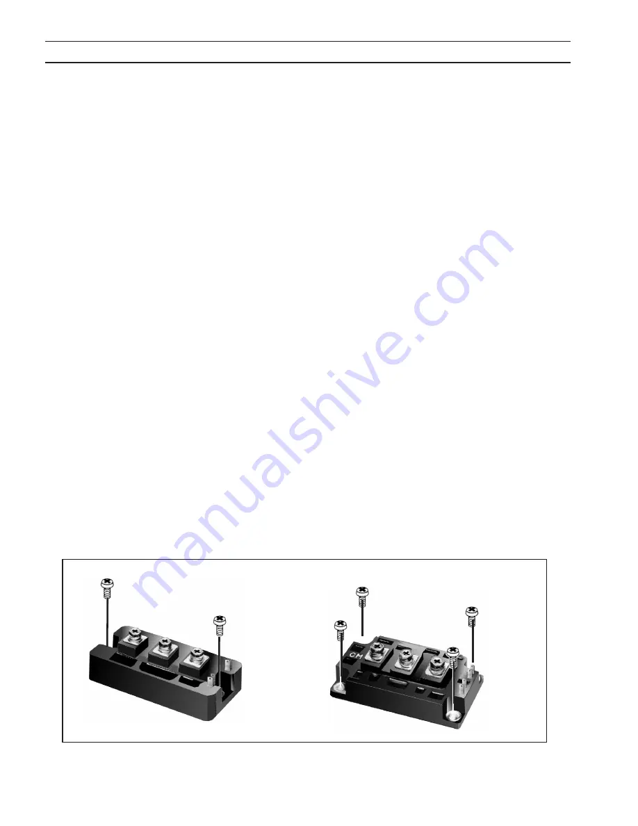
Two-Point Mounting Type
Initial tightening
Final tightening
Four-Point Mounting Type
Initial tightening
Final tightening
figure 5-5. screw fastening order
When mounting modules on a heatsink, certain precautions should be taken to prevent any damage against a sudden
torque. If a sudden torque (“one-sided tightening”) is applied at only one mounting terminal the ceramic insulation plate
or silicon chip inside the module may get damaged.
The mounting screws are to be fastened in the order shown below. Also, care must be taken to achieve maximum contact
(i.e. minimum contact thermal resistance) for the best heat dissipation.
A torque wrench should be used. Tighten mounting and terminal screws per Torque Requirements shown in Subsection 7.3.
If device is over-torqued, the device can be damaged like the above “one-sided tightening”.
Application of a Thermal Compound or Thermal Pad on the contact surface is required to properly remove heat from the
device. It is recommended that a unit manufactured with thermal compound use thermal compound for replacement, even
if replacement module was shipped with a thermal pad. Thermal compound may always be used as a replacement for a
pad. Never use both compound and a pad.
Thoroughly remove any residual material from the mating surfaces. Use Dow-340 Heat Sink Compound or equivalent. Apply
a thin layer (.005” nominal) between mating surfaces. If a thermal pad is used, ensure there are no folds or creases.
Since IGBT gates are insulated from any other conducting region, care should be taken to prevent static build up, which
could possibly damage gate oxides. All IGBT modules are shipped from the factory with conductive foam contacting the
gate and emitter sense pins.
Always ground parts touching gate pins during installation. In general, standard ESD precautions application to FETs should
be followed.
Other handling precautions that should also be observed are as follows:
•
Use grounded work station with grounded floors and grounded wrist straps when handling devices.
•
Use a 100
Ω
resistor in series with the gate when performing curve tracer tests.
•
Never install devices into systems with power connected to the system.
Summary of Contents for ESP-101
Page 4: ...4 table of contents...
Page 8: ...8 TABLE OF CONTENTS...
Page 38: ...38 section 4 operation...
Page 42: ...42 TABLE DES MATI RES...
Page 72: ...72 section 4 exploitation...
Page 76: ...76 NDICE...
Page 106: ...106 SECCI N 4 FUNCIONAMIENTO...
Page 110: ...110 NDICE...
Page 140: ...140 Se o 4 opera o...
Page 144: ...144 INDICE...
Page 174: ...174 sezione 4 funzionamento...
Page 178: ...178 INHALTSVERZEICHNIS...
Page 208: ...208 ABSCHNITT 4 Betrieb...
Page 209: ...ESP 101 0558007871 ESP 101 PxxJ943xxx 0558004880 ESP 101 460 V 0558005215 ESP 101 380 400V CE...
Page 210: ...210 52 529...
Page 212: ...212...
Page 213: ...213 1 1 0 ESAB 1 2 3 4 5 IP 12 mm 60 IP23S 15 15...
Page 214: ...214 1...
Page 215: ...215 2 2 1 ESP 101 PT 37 ESP 101 PT 37 1 1 4 32 mm ESP 101 2 2 ESP 101 ESABPT 37PLASMARC...
Page 224: ...224 3 3 4 3 5 2 Slo Blo 2 Amp 600 V 90 150 psi 6 2 10 3 bar...
Page 229: ...229 3 1 ESP 101 2 3 4 5 6 3 9 PT 37...
Page 231: ...231 3 A ESP 101 1 2 3 8...
Page 232: ...232 B RJB 1 2 RJB 3 1...
Page 233: ...233 3 ESP 101 PT 37 2 RJB 3 PT 37 RJB 4 ESP 101 3 9...
Page 234: ...234 3 ESP 101 ESP 101 PT 37 1 ESP 101 2 3 4 5...
Page 239: ...239 4 4 1 4 6 4 mm A B A B 4 4 4 5 4...
Page 240: ...240 5 volt 4 5 5 volt 4 6 4...
Page 241: ...241 4 6 ESP 101 ESAB A 1 2 3 4 5 6 B 1 2 3 1 2 3 4 5 1 2 3 4 5 1 2 1 2 3 1 2 3 H 1 2 3 4 4...
Page 242: ...242 4...
Page 246: ...246 OBSAH...
Page 276: ...276 odd l 4 provoz...
Page 290: ......


