MT CAM AG_v1.doc
MT STAR AG
Indice : 1
18/10/2016
9 /
25
ERECA SAS 75 rue d'Orgemont, 95210 SAINT GRATIEN France
Tel +33 1 39 89 76 23 www.ereca.fr
2.3.10.2 BASESTATION PINOUT
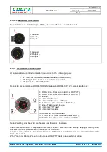
Basestation are on standard 3 pins XLR’s, pinout is as follows for each channels.
1: Ground,
2: Input +,
3: Input -.
1: Ground,
2: ,
3: Output -.
2.3.11 OPTIONNAL CONNECTOR
At camera side an optional connector give access to the following signals
•
2
nd
Intercom in/out with headset interface at camera side,
•
2
nd
Tally (Green) Contact closure from basestation,
•
2
nd
Serial data RS 232/422/485.
Connector socket is Hirose HR10A-10R-12S (mate with HR10A-10P-12P), pinout is a follows:
1: RX RS 422 – (Cam racer electrical OUTPUT),
2: RX RS 422 + (Cam racer electrical OUTPUT),
3: Ground,
4: Intercom 2 Mic input +,
5: Intercom 2 Mic input - / Shield,
6: +14V output (1A internal resettable fuse),
7: Green Tally ground closure,
8: Intercom 2 PTT input,
9: Intercom 2 Earpiece,
10: Reserved / Do not connect,
11: TX RS 422 + (Cam racer electrical INPUT),
12: TX RS 422 - (Cam racer electrical INPUT).
Serial 2 settings and behavior are the same as for serial 1 interface.
Intercom 2 will work only if “separated intercoms” choice is selected in the settings webpage. Settings and
and electrical specifications are the same as for intercom 1.
In this case only channel 1 is routed to intercom 1 XLR socket and channel 2 is routed to intercom 2 on this
Hirose 12 socket.
When “monoral intercom” is set pin 8 acts as a third PTT input to ease external wiring.

