background image


MT CAM AG_v1.doc


MT STAR AG 

Indice : 1 

18/10/2016 


13 / 

25


ERECA SAS  75 rue d'Orgemont, 95210 SAINT GRATIEN France 

Tel +33 1 39 89 76 23    www.ereca.fr 


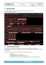
2.4.1.3  MODE 3 INTERCOM TALK  

 
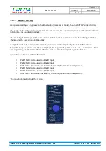
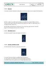
The purpose of this mode is only to indicate visually that an intercom channel is used. The two examples 
shown below illustrate what happen for each channel, note that the setup led is blinking. 
 
The meaning of the “major status” and “various status” sections remain the same. 


                                                    Talk on channel 1                                                          Talk on channel 2 


2.4.2  BASESTATION 


2.4.2.1  OLED DISPLAY AND ROTARY BUTTON 

 
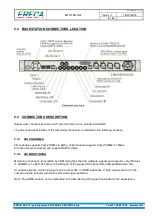
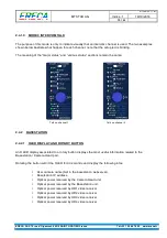
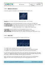
An OLED display associated to a rotary button displays the most useful information related to the 
Basestation / Camera Head pair. 
 
Rotating the button will lit the OLED for 30 seconds and display the following infos: 


User camera name (Set in the basestation webserver), 


Basetsation IP address, 


Optical power received by the Camera Head unit, 


Optical power received by the Basestation unit, 


Optical power received by HD1 video receiver, 


Optical power received by HD2 video receiver, 


Optical power received by HD3 video receiver, 


Optical power received by HD4 video receiver. 


Summary of Contents for CAM RACER

Page 1: ...dice 1 18 10 2016 1 25 ERECA SAS 75 rue d Orgemont 95210 SAINT GRATIEN France Tel 33 1 39 89 76 23 www ereca fr C CA AM M R RA AC CE ER R 12G SDI Dockable optical fiber transmission unit for HD 3G 4K 8K Camera TECHNICAL PRESENTATION ...

Page 2: ...audio 8 2 3 11 Optionnal connector 9 2 3 12 Lanc connector 10 2 3 13 Optical Connectors 10 2 4 Display unit 11 2 4 1 Camera head 11 2 4 2 Basestation 13 2 5 Remote power section 16 2 5 1 Main power section 16 2 5 2 8 4V regultator option 16 2 6 Audio mixer 17 2 7 Intercom behaviour 17 2 7 1 2 channels intercom 17 2 7 2 Separate intercoms 18 3 WEB MANAGEMENT 18 3 1 Essentials 18 3 2 Status page 19 ...

Page 3: ... An internal audio mixer allows user to mix between talkback programs inputs and local audio channels for Eng and Reporter headsets Camera control channel supports Ethernet RS422 Serial Canon RC V100 protocol Enhanced Lanc Camera synchronization supports Two composite video signals and one Time code 1 2 SIGNAL CAPACITY Each CAM Racer comes in standard with the following signal set 2 3G HD SD signa...

Page 4: ...rogram2 listen level and push to talk commands Red green tally led are located on top of the unit Cooling of the unit is done by a small and silent fan located at the back of the unit The basestation receiver is integrated in a standard 19 1RU format All signals are dispatched on standard connectors and standard pinout at the rear of the chassis Web server is on a separate Ethernet port The front ...

Page 5: ... channels supports from 270Mbs to 3Gbs 12G channels supports from 270Mbs to 12Gbs All channels are reclocked and support RAW formats 2 3 2 SDI MONITORING Monitoring channel is transmitted by TDM along the other low datarate signals and supports only HD rates 1 485GBs or 1 485 1 001 Gbs the ANC part of the signal SDI is transmitted Embedded audio etc At camera side the monitoring input can be eithe...

Page 6: ... bitrate is 500 Kbds For RS485 also setup the corresponding Baud rate within the web server to enable the cam racer to manage output impedance at the right serial byte duration Shorting pin 1 and 2 will trigger the Intercom for talking on channel 1 Pins 7 and 8 are shorted at camera side Floating dry contact when tally RED is triggered at base station 1 8 1 GND Shield for serial channel 2 PTT inpu...

Page 7: ...ted on a DSUB 25 Female connector with same pinout as other popular CCU s Socket contact D SUB 25 Intercom Tally Socket contact SIGNAL 1 25 14 13 Intercom 1 OUT 1 14 Intercom 2 OUT Intercom 1 OUT 2 15 Intercom 2 OUT GND 3 16 GND Intercom 1 IN 4 17 Intercom 2 IN Intercom 1 IN 5 18 Intercom 2 IN PGM1 IN 6 19 PGM1 IN PGM1 IN 7 20 PGM1 IN GND 8 21 GND GND 9 22 AUX4 input AUX3 input 10 23 AUX5 input RE...

Page 8: ...t impedance of the earpiece amplifier is 20 Ohms and suitable for 50 to 600 Ohms headsets 1 Mic input or Mic Shield 2 Mic input 3 Ground for Earpiece 4 Ear piece 5 NC default or special use see note Note Upon request pin 5 can either be shorted internally to pin 4 for stereo headsets or routed on the output of the second headphone amplifier to hear only the second intercom channel on pin 5 2 3 10 ...

Page 9: ...a follows 1 RX RS 422 Cam racer electrical OUTPUT 2 RX RS 422 Cam racer electrical OUTPUT 3 Ground 4 Intercom 2 Mic input 5 Intercom 2 Mic input Shield 6 14V output 1A internal resettable fuse 7 Green Tally ground closure 8 Intercom 2 PTT input 9 Intercom 2 Earpiece 10 Reserved Do not connect 11 TX RS 422 Cam racer electrical INPUT 12 TX RS 422 Cam racer electrical INPUT Serial 2 settings and beha...

Page 10: ...st to leave the ring unconnected in your cable Caution Lanc management is not symmetric the camera must be connected on camera head unit and the remote connected on the basestation unit 2 3 13 OPTICAL CONNECTORS The CAM Racer stage racer uses the two fibers of the SMPTE cable for signal transmission One fiber is used bidirectionally with a 2 5Gbs TDM signal carrying all the low datarate signals an...

Page 11: ...o low or too high laser current Various signal status TIMECODE Green LED ON when timecode is delivered on the camera unit output AUDIO IN Green LED ON when the optical power is low on main path AUDIO OUT Green LED ON when the optical power is low on main path if option fitted PAL1 Green LED ON when a composite trilevel video is delivered on the camera unit output 1 PAL2 Green LED ON when a composi...

Page 12: ...exts written in blue apply A single led will be lit in this section indicating what level will be adjusted by the blue button rotation On each short press Less than 0 5 second the indicating led will point the next level if not desired short press again to go to the desired level After the sixth level the led will point again the first one Adjustable levels are scrolled in this order PGM1 INC1 Lis...

Page 13: ...on channel 1 Talk on channel 2 2 4 2 BASESTATION 2 4 2 1 OLED DISPLAY AND ROTARY BUTTON An OLED display associated to a rotary button displays the most useful information related to the Basestation Camera Head pair Rotating the button will lit the OLED for 30 seconds and display the following infos User camera name Set in the basestation webserver Basetsation IP address Optical power received by t...

Page 14: ...on internal temperature is over 60 C RMT PSU ALARM Red LED ON when the source voltage of the remote power supply section is low 2 4 2 3 AUDIO LED S Audio presence activity at basestation level is displayed in this section The AUDIO section indicates presence of signal on the noble audios XLR s The PGM section indicates presence of signal on Program inputs of the basestation DSUB 25 The INCOM secti...

Page 15: ... and re create the corresponding clock of the signal fed at the camera unit HD IN indicates that a SDI signal is detected on the corresponding input whatever its data rate Note The monitoring input will only work on a HD rate 2 4 2 5 REFERENCE LED S All reference signals for camera are grouped in this section 2 4 2 6 CONTROL CHANNELS LED S All control channels link activity are grouped in this sec...

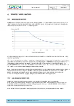
Page 16: ...wer regarding the loss of the installed SMPTE cable In this case the CAM racer will detect power drop and will switch on the battery and come back on the remote power supply to save battery energy Note The power curve above represents power dissipated by a pure resistive load camera inrush current or accessories inrush current may exceed those limits and make the internal converter to stop briefly...

Page 17: ...gs pages to Save Recover settings from your computer 2 7 INTERCOM BEHAVIOUR Intercom have 2 operation modes Single headset with 2 channels Most common Separate headset with 1 channel on each headset The selection is done with the combo box named Intercom mode The Talk Talk latch action can be done directly on the camera unit or trough ground closures located at SERIAL 1 RJ45 or on the Hirose12 Mul...

Page 18: ...l move on the webpage but is no more responsive to any change attempt made on the web page for a small amount of time 1 second 3 1 ESSENTIALS The CAM RACER is monitored and configured through WEB interface Firefox web browser preferred The RJ45 Ethernet ADMIN port of the basestation provides access to the embedded web server interface Note this network have no relation with the remote camera remot...

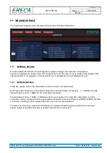
Page 19: ...oint of view as what happen on this unit connectors The signals are grouped in category easily recognizable thanks to the pictograms attached to each category The video section is more detailed with the detected data rate colored indication Datarate is only recognized on receiver s channels 3 2 2 ALARMS DISPLAY The unit global technical status alarm are summarized in the 3 lower categories Power s...

Page 20: ...l displayed in red 3 3 2 OPTICAL DETAILS These two groups monitor the basestation and the camera unit optical state Each figure will change color if the alarm threshold is reached 60mA for the laser 18dBm for the 3G optical receivers and 13dBm for the 12G optical receivers The optical level below 18dBm 13dBm warns the user against a too high fiber attenuation or a dirty connection it does not mean...

Page 21: ... 3 4 1 MICROPHONES SUB SECTION The XLR Mic group sets the mode and the gain of the 2 noble audio inputs on the camera unit Use can select Line or activate an internal Mic gain bloc with or without phantom power injection by ticking the right boxes The Intercom Mic group sets the mic input gain and type from the list below Dynamic Asymmetric dynamic most common Electret or Carbon 8 V 470 Ohms polar...

Page 22: ...s all the single simple configuration commands as Serial interface levels RS232 422 485 Tally input levels and Led disable Intercom forgotten in talk position can be released here by ticking the right box Lanc protocol selection Legacy RCV 100 Works only with RC V100 Turn Composite 1 input to high impedance Disable all the leds on the cam racer unit 3 4 4 SAVE RECALL User can Download Browse Impor...

Page 23: ...lick on initial values Note If IP add is lost press RST switch at the rear of the unit for 5 seconds the unit will revert to default settings or use the rotary button to read it on the Oled display 3 5 2 IP ADDRESS Setup the IP address of the unit after validation with the password the unit instantaneously switches to the new IP settings an internet link route the user to the new address Default I...

Page 24: ...6 24 25 ERECA SAS 75 rue d Orgemont 95210 SAINT GRATIEN France Tel 33 1 39 89 76 23 www ereca fr 3 5 4 CHANGE PASSWORD Simply type twice the new general password in the Modification of password section and validate with the commit changes procedure ...

Page 25: ... LANC Number connector 1 bidirectionnal Jack2 5mm Protocol Standard LANC or RC V100 remote protocol 5V open collector signaling Data Number connector 2 bidirectional channel RJ 45 for Channel 1 Hirose 12 for channel 2 Protocols RS485 RS422 RS232 Data rate 0 to 500 Kbd s Ethernet Number connector 1 channel RJ 45 Protocols 10 or 100 Mb s Full or Half duplex Auto sense MDI or MDI X Auto sense Interco...

Reviews: