MT CAM AG_v1.doc
MT STAR AG
Indice : 1
18/10/2016
7 /
25
ERECA SAS 75 rue d'Orgemont, 95210 SAINT GRATIEN France
Tel +33 1 39 89 76 23 www.ereca.fr
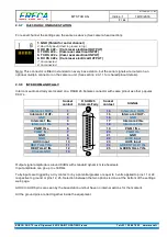
2.3.7 RJ45 DATA2 ON BASE STATION
For serial channel the settings are the same as above (See camera head section).
1
8
1: GND (Shield for serial channel)
2: Red Tally input (Short to ground to trig)
3: RX RS 422 – (Cam racer electrical OUTPUT)
4: TX RS 422 – (Cam racer electrical INPUT)
5: TX RS 422 + (Cam racer electrical INPUT)
6: RX RS 422 + (Cam racer electrical OUTPUT)
7: Unconnected
8: Unconnected
Note: This connector is fitted in standard on every base station, but the serial signals are routed on an
optional multipin connector on the camera unit. (See section 2.3.1.1 for shared pinout details).
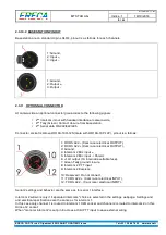
2.3.8 INTERCOM AND TALLY
Intercom audio and tally are located on a DSUB 25 Female connector with same pinout as other popular
CCU’s.
Socket
contact
D SUB 25
Intercom/Tally
Socket
contact
SIGNAL
1
25
14
13
Intercom 1 OUT+
1
14
Intercom 2 OUT+
Intercom 1 OUT-
2
15
Intercom 2 OUT-
GND
3
16
GND
Intercom 1 IN+
4
17
Intercom 2 IN+
Intercom 1 IN-
5
18
Intercom 2 IN-
PGM1 IN +
6
19
PGM1 IN +
PGM1 IN -
7
20
PGM1 IN -
GND
8
21
GND
GND
9
22
AUX4 input
AUX3 input
10
23
AUX5 input
RED TALLY IN+
11
24
GREEN TALLY IN+
RED TALLY IN-
12
25
GREEN TALLY IN-
Chassis GND
13
Output signal amplitude is around 0dBm with standard dynamic mike headsets.
Input amplitude can go up to +18Dbm.
Tally inputs are trigged by a dry contact or by a potential greater or equal to 5 volts applied to pins 11 or 24
respective to ground or pins 12, 25. Selection between the two options is done at the bottom of the settings
web page.
AUX3 to AUX5 pins are seen by the basestation unit but have no internal actions for the moment.
All the ground pins are tied together inside the equipment.


