English
Rev. 1.0.3 / 2010-10-27
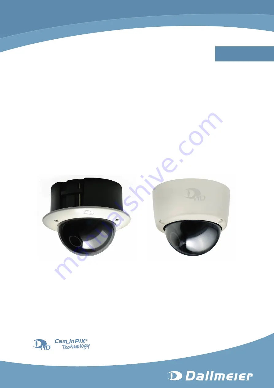
Installation and Configuration
Vandal-resistant High Definition IP Dome Camera
DDF4500HDV
720p
-SM
(Surface Mount Variant)
-IM
(In-ceiling Mount Variant)
DDF4900HDV
1080p
Page 1: ...English Rev 1 0 3 2010 10 27 Installation and Configuration Vandal resistant High Definition IP Dome Camera DDF4500HDV 720p SM Surface Mount Variant IM In ceiling Mount Variant DDF4900HDV 1080p ...
Page 2: ...hweg 1 93051 Regensburg Germany www dallmeier com info dallmeier com All trademarks identified by are registered trademarks of Dallmeier electronic All trademarks identified by are trademarks or registered trademarks of the following owners Adobe and Flash of Adobe Systems Incorporated headquartered in San José California USA IBM of International Business Machines Corporation headquartered in Armo...
Page 3: ...ion 12 5 Views and Connection Assignment 13 5 1 In ceiling Mount Variant 13 5 2 Surface Mount Variant 15 5 3 Camera Module 17 6 Installation and Commissioning 18 6 1 In ceiling Mount Variant 18 6 2 Surface Mount Variant 23 7 Connection and Login 24 7 1 System Requirements 24 7 2 Connection 24 7 3 Login 26 8 Basic Settings 28 8 1 Language 28 8 2 System Time 28 8 2 1 Manual Configuration 29 8 2 2 Ti...
Page 4: ...Optimization 49 10 3 Encoder Settings 50 10 3 1 Encoder 1 50 10 3 2 Encoder 2 52 10 3 3 Encoder 3 52 10 3 4 Audio 53 11 Interfaces 54 11 1 Data Display 54 11 1 1 Filter 54 11 1 2 Position 55 12 Service and Info 57 12 1 Activations 57 12 2 Event Log 57 12 3 Configuration File 58 12 3 1 Download 58 12 3 2 Upload 58 12 3 2 1 Configuration Recovery 59 12 3 2 2 Configuration Transfer to Several Devices...
Page 5: ...DDF4900HDV DDF4500HDV www dallmeier com 5 17 Technical Drawings 69 17 1 In ceiling Mount Variant 69 17 2 Surface Mount Variant 70 ...
Page 6: ... be made between the device variants the complete product names will be mentioned Pictures in this document may differ from the actual product 1 2 Documents Commissioning The document entitled Commissioning contains the most important steps for the connec tion and commissioning of the device Installation and Configuration this document The document entitled Installation and Configuration contains ...
Page 7: ...r serious injury Caution CAUTION indicates a hazardous situation which if not avoided could result in minor or moderate injury Notice NOTICE indicates practices for preventing property damage incorrect configurations or faulty operations Instructions are indicated by arrows Expressions in bold italics generally indicate a control element on the device switches or labels or on its user interface bu...
Page 8: ...in loss of warranty Modifications Do not make any modifications to the hardware or software that has not been tested and approved by Dallmeier Inappropriate modifications can cause malfunctions damages and data loss and can result in loss of warranty Documentation Carefully and completely read the documents included in delivery Always observe the contained instructions notes and warnings Condensat...
Page 9: ... the power supply pull out the power plug Contact the sales partner responsible for your area Opening The housing of the unit may only be opened by qualified personnel for commissioning inspection maintenance and repair Disposal Disconnect the unit from the power supply Remove all connected devices Return the unit to your respective sales partner ...
Page 10: ...ble ensure that the packaging used sufficiently protects the unit against damage moisture heat and cold 3 3 Appropriate Use The DDF4900HDV DDF4500HDV is a vandal resistant High Definition IP dome camera The in ceiling mount variant is designed for indoor installations in suspend ed ceilings the surface mount variant for indoor installations on ceilings and walls All de vice variants can be operate...
Page 11: ...ce mount variant only DIN EN 50130 4 compliant For detailed information see chapter Technical Data on page 67 3 5 Warranty The terms and conditions valid at the signing of the contract shall apply 3 6 Approvals Certifications Following approvals certifications were valid at the time of document compilation Refer to www dallmeier com for possible updates CE DIN 50130 4 compliant ...
Page 12: ... over Ethernet 4 3 Outdoor Surface Mount Variant only For outdoor installations surface mount variant only use only IP67 approved components and assemblies e g sealing rings cable gland To extend the product life cycle protect the device from direct influence of weather condi tions rainfall insolation Therefore we recommend a protected installation site e g under a projecting roof 4 4 Operation Ob...
Page 13: ...com 13 5 Views and Connection Assignment 5 1 In ceiling Mount Variant Thread for M6 screw eye bolt Housing Trim ring with bubble 3 axis mount pan tilt rotation Thread for PG16 cable gland Lens Ceiling clamp Housing screw T20 Torx Fig 5 1 ...
Page 14: ...ng clamp Thread for PG16 cable gland DC auto iris interface for iris control Cable fastener Cable fastener Video preview output BNC CVBS Locking screw focal length Locking screw focus Thread for housing screw Thread for housing screw Thread for housing screw Camera module Fig 5 2 Housing top view ...
Page 15: ...DF4500HDV www dallmeier com 15 5 2 Surface Mount Variant Thread for PG16 cable gland Mounting hole for Ø4mm screw Housing base Housing with bubble Housing screw T20 Torx Lens 3 axis mount pan tilt rotation Fig 5 3 ...
Page 16: ...ole for Ø4mm screw DC auto iris interface for iris control Cable fastener Cable fastener Video preview output BNC CVBS Locking screw focal length Locking screw focus Thread for PG16 cable gland Camera module Thread for housing screw Thread for housing screw Thread for housing screw Fig 5 4 Housing base top view ...
Page 17: ...le LAN PoE RJ45 jack DC auto iris interface for iris control Locking screw rotation z axis Audio OUT 3 5mm phone jack Power IN 12V DC SDHC card Locking screw rotation z axis Not included in the standard scope of delivery 3 axis mount pan tilt rotation Fig 5 5 ...
Page 18: ...for the ceiling wall material Use the correct type of anchor for your ceiling wall type Plastic screw anchors for solid wall material concrete brick Toggle bolt style anchors for drywall hollow wall type plaster Electric shock hazard Danger of death or serious injury Disconnect the power supply unit from the mains socket before connect ing the device In order to comply with the UL requirements you...
Page 19: ...using a drywall utility saw or a jigsaw Screw the M6 screw eye bolt on the bottom side of the housing Unscrew the 3 housing screws using a T20 torx wrench and remove the trim ring Suspended ceiling Ø143mm M6 screw eye bolt Ceiling clamp Trim ring with bubble PG16 cable gland Housing screw T20 Torx Fig 6 1 ...
Page 20: ...a carabiner and the ceiling hook Run the required cables suspended from the ceiling through a PG16 cable gland Screw the PG16 cable gland in the appropriate thread of the housing Insert the housing into the circular recess Carabiner Safety wire Supporting structure Ceiling hook Suspended ceiling Ceiling clamp PG16 cable gland M6 screw eye bolt Fig 6 2 ...
Page 21: ... the M4 locking screw Fig 5 2 of both ceiling clamps with a Phillips screw driver until the housing is fixed Fig 6 4 Ceiling clamp Ceiling clamp Suspended ceiling Phillips screwdriver Fig 6 3 Locked ceiling clamp Locked ceiling clamp Suspended ceiling Fig 6 4 ...
Page 22: ...e mains socket Connect a CVBS monitor to the video preview output Fig 5 2 Adjust the lens direction using the 3 axis mount and set the focal length and focus Disconnect the CVBS monitor Attach the trim ring to the housing and tighten the 3 housing screws using a T20 torx wrench Housing screw T20 Torx Locked ceiling clamp Locked ceiling clamp Suspended ceiling Trim ring with bubble Fig 6 5 ...
Page 23: ...material in the drill holes Run the required cables suspended from the ceiling wall through a PG16 cable gland Screw the PG16 cable gland in the appropriate thread of the housing base Mount the housing base with 3 screws to the ceiling wall Ceiling Wall Drill hole Anchor Mounting screw Ø4mm Thread for PG16 cable gland Housing base Fig 6 6 Connect the required cables to the connectors of the camera...
Page 24: ...te that a more powerful PC is required if several devices are configured with live video display simultaneously a DirectX compatible graphics card and the Dallmeier control for ActiveX are not re quired for the configuration without live video display the Dallmeier control for ActiveX can be downloaded from the Dallmeier Partner Forum the Dallmeier control for ActiveX can be automatically download...
Page 25: ...bar B Switch between live and configuration mode C Live video D Adjust video resolution E IP address of device F Log out of configuration mode Note the explanations below Hide the title bar A if required Activate the Networks with routers NAT checkbox if required Adjust the live video resolution D if required This resolution setting only affects the live video display in the web browser and is not...
Page 26: ...data packets the port 30000 for the DaVid Protocol1 and port 80 for the Hypertext Transfer Protocol HTTP must be open Note that at data transmission over TCP normally no packet loss lack of images occurs short term peaks in network traffic may occur low delays may occur The Networks with routers NAT function does not affect the Video streaming function see section Video Streaming on page 45 7 3 Lo...
Page 27: ... bar B Switch between live and configuration mode C IP address of device D Log out of configuration mode E Disable enable live video display F Live video G Configuration menu H Configuration dialogues Note that the live video display in the configuration mode can be disabled if only a low bandwidth is available a new login is required after 5 minutes without user action ...
Page 28: ...ogue via Common settings User interface Fig 8 1 Set the Language Deactivate the Show live video ActiveX in WebConfig checkbox if network bottle necks occur or your system is overloaded Confirm with OK 8 2 System Time The system time can be set manually or synchronized with a UTC time server The time zone must be set in both cases Open the Time settings dialogue via Common Settings Time Select the ...
Page 29: ...tion is enabled Select the Date Time tab Fig 8 3 Set the Date Set the Time Confirm with OK 8 2 2 Time Server Note that the time server must always be accessible via the network Select the Time server tab Fig 8 4 Enter the IP address of the time server Activate the Use time server checkbox to enable the UTC time server synchronization Confirm with OK ...
Page 30: ... user groups In addition several users can be assigned to each user group if required 8 4 1 Login Mode The configuration of the device is only possible after a successful authentication as a valid user The login mode defines the type of authentication Mode Type Group login Group password User login User name user password or Group password The authentication with the group password is also possibl...
Page 31: ...r security reasons Group 2 user and Group 3 guest are defined without a factory default password a login of Group 2 user and Group 3 guest is only possible after a password is de fined Open the User groups dialogue via Common settings User management User groups Fig 8 7 Select the tab of the relevant group Enter a new Group name if required Enter a New password Repeat the new password in the Confi...
Page 32: ...a User Ensure that the Login mode is set to User login Open the User groups dialogue via Common settings User management User groups Fig 8 8 Select the tab of the relevant group Click New The New user dialogue is displayed Fig 8 9 Enter a new User name Enter a New password Repeat the new password in the Confirm password field Finally confirm with OK ...
Page 33: ...ed button 8 4 4 Rights The three user groups and so the assigned users can be granted individual rights Ad ditionally the general public user group anonymous can be granted or denied access to certain types of live images Note that the rights of Group 1 admin can not be restricted certain rights can not be set to all permission levels certain rights are partially or fully relevant for external app...
Page 34: ...isplayed The settings can be changed The function can be used allow read only The dialogue will be displayed The settings can not be changed deny The dialogue will not be displayed The settings can not be changed The function can not be used Find the relevant right line Change the permission level with a click on the symbol in the column of the relevant group Proceed as described above for all rig...
Page 35: ...rk Basic settings Fig 9 1 Network settings and MAC address Factory Settings Connection type automatic DHCP deactivated Hostname ipcam IP address 192 168 2 28 Netmask 255 255 255 0 Gateway 192 168 2 1 Allow IP Finder network configuration activated Notice Incorrect settings may result in the device being no longer available via the network For troubleshooting purposes write down the MAC address and...
Page 36: ...ion to the device is terminated and the new network settings are assigned 9 1 2 DHCP To automatically assign the network settings by a DHCP server proceed as follows Ensure that an active DHCP server is available in the local area network LAN Activate the DHCP checkbox Deactivate the Allow IP Finder network configuration checkbox if not required Finally confirm with OK The connection to the device...
Page 37: ... Click Network Alarm hosts New The configuration menu is expanded with the Alarm host 1 item and the related dialogue is displayed To edit an already set alarm host click the related item in the configuration menu 9 2 1 Settings Select the Settings tab Fig 9 2 Enter the name of the alarm host into the Name field Enter the IP address of the alarm host Activate the active checkbox to enable the mess...
Page 38: ...d check box Confirm with OK 9 2 3 Scheduler The scheduler function allows scheduling the messaging function Note that scheduler settings only apply to the currently selected alarm host the minimum selectable period is 15 minutes the week timer applies to the entire year if no exceptions are set 9 2 3 1 Week Timer Click Scheduler The Week timer tab is displayed Fig 9 4 ...
Page 39: ...the week timer represent inactive periods During inactive periods the messaging function is disabled In the example shown Fig 9 5 the period on Monday from 02 00 to 07 15 am is inactive During this period no messages are sent out Confirm with OK if you do not want to make any additional settings Delete Inactive Periods Click active In the week timer click and hold the left mouse button and draw a ...
Page 40: ...tions exceptions can be defined Note that exceptions will overwrite the settings of the entire relevant day in the week timer Select the Exceptions tab Fig 9 6 Click New The Calendar is displayed Fig 9 7 Select a date Confirm with OK The selected date is added to the exceptions list ...
Page 41: ...ble click and hold the left mouse button and draw a rectangle over a rel evant period Release the mouse button Repeat the last two steps until all relevant active periods are selected Fig 9 9 Light gray areas in the timetable represent active periods During active periods the messaging function is enabled In the example shown Fig 9 9 the period from 02 00 to 06 00 am is active During this period m...
Page 42: ...s are deleted It is also possible to delete sections at least 15 minutes between active periods If the exception settings should also apply to other days they can be can copied to another date see below Confirm with OK if you do not want to make any additional settings 9 2 3 3 Copy Exceptions Select a date from the exceptions list Click Copy The Calendar is displayed Fig 9 10 Select the new date t...
Page 43: ...do not want to make any additional settings 9 2 4 Copy The copy function allows copying the saved settings to other alarm hosts entries Click Network Alarm hosts Select a saved alarm host entry from the configuration menu The related dialogue is displayed Fig 9 12 Click Copy The configuration menu is expanded with the name of the copied alarm host entry with the addition 1 represents copy 1 and th...
Page 44: ... 5 Delete Alarm Host Entry To delete an alarm host entry proceed as follows Click Network Alarm hosts Select the alarm host entry to be deleted from the configuration menu The related dialogue is displayed Fig 9 14 Click Delete The alarm host entry is deleted and its menu item removed from the configuration menu ...
Page 45: ...planations below Select the encoder from the drop down list Input Select the transfer protocol format and method from the drop down list Mode Depending on the selected transfer method enter the Multicast IP address or the Destination IP address Enter the port number of the service which should receive the data packets into the Port 1024 65535 field Enter the TTL value of IP packets into the TTL 0 ...
Page 46: ...yload Format for JPEG compressed Video 9 3 2 Transfer Method The transfer method defines the distribution of audio and video data in the network Multicast The data packets are transferred via point to multipoint connection to a group of receivers clients including the specified IP multicast address and port number The packets have to be transferred only once the distribution to the members of the ...
Page 47: ... If the value is zero 0 the IP packet is discarded While preventing IP packets from endlessly circulating in the network due to routing errors this method stops IP packets from breaking through the limits of the LAN and being sent to the WAN TTL 1 According to requirements a TTL value from 1 255 can be entered When entering 0 zero the default values are used TTL 1 for multicast TTL 64 for unicast ...
Page 48: ... device HD 25 50 fps for PAL countries HD 30 60 fps for NTSC countries Open the Video standard dialogue via Video Video standard Fig 10 1 Note that this dialogue may be locked by external devices applications Select a Standard Confirm with OK 10 2 Sensor The sensor settings provide the configuration of the image sensor and the adjustment of the image processing parameters to the local situation Op...
Page 49: ...for outdoor scenes Indoor recommended for indoor scenes Low light recommended for scenes with low light conditions Lens DC control for lenses with DC auto iris control Backlight Backlight compensation enabled On or disabled Off 10 2 2 Image Optimization In the Image optimization tab the following settings can be configured Fig 10 3 Brightness Defines the overall image brightness by linear adjustme...
Page 50: ... For this the Encoder 1 which has to be set to H 264 encoding is used Encoder 2 and 3 are automatically disabled In addition to the recording a second stream from Encoder 1 can be used for the live display if the Encoder 1 is set to a bit rate not higher than 6 MBit 10 3 1 Encoder 1 Open the Encoder settings dialogue via Video Encoder settings The Encoder 1 tab is displayed Fig 10 4 Note the expla...
Page 51: ... May cause loss of detail Frames Second The frame rate value in fps defines the number of consecutive frames produced per sec ond The higher the frame rate is the smoother the video playback Bitrate The bit rate refers to the number of bits per second used to encode the video The more bits are used to represent the video data per second the higher the quality is Low bit rate High image compression...
Page 52: ...al ap plications e g in multiplex mode GOP sizes greater than 15 belong to the extended GOPs Reverse playback has limited quality frame drops with extended GOPs GOP size 15 10 3 2 Encoder 2 Encoder 2 is disabled by default Note that the Encoder 2 option is dependent on the set frame rate and resolution of En coder 1 Select the Encoder 2 tab Fig 10 5 If required activate the Use encoder checkbox to...
Page 53: ...o Audio encoding is not supported in this software version The audio bit rate setting allows you not only to control the audio quality but also the amount of required hard disk space to a certain extent The higher the audio bit rate the better the audio quality A higher bit rate however requires more hard disk space than a lower bit rate Select the Audio tab Fig 10 7 Select the Audiobitrate Confir...
Page 54: ... Filter The external transferred data can be filtered before embedding The filtering selection only takes effect on external sent data Open the Data display Filter dialogue via Interfaces Data display Filter Fig 11 1 By default no external transferred data is embedded To embed external transferred data proceed as follows Activate the Display active checkbox Select the relevant data by activating t...
Page 55: ...ts a screen for displaying live videos with full PAL or NTSC resolution The white lines illustrate the stylized graphical user interface GUI of a typical application for displaying live videos The white rectangle with the yellow corner in the bottom right shows the display area of the embedded data On the left hand side of the dialogue the coordinates and dimensions of the display area are display...
Page 56: ...eier com 56 The display area can be resized by dragging its yellow corner in the bottom right Fig 11 4 An exact positioning and resizing is possible by using the corresponding input fields Adjust all relevant settings Confirm with OK ...
Page 57: ... For purchasing activation codes contact the Dallmeier Sales Department Open the Activations dialogue via Service Activations Fig 12 1 Enter the Activation code Confirm with OK 12 2 Event Log The device logs IP addresses of applications that temporarily blocked certain resources of the device in a log file The list of IP addresses is displayed in the Event log dialogue Open the Event log dialogue ...
Page 58: ...e Download Fig 12 3 Select all relevant settings which should be exported to the configuration file by activat ing the related checkbox Confirm with OK Follow the instructions of the download dialogue and save the configuration file to a data storage device The configuration file name contains the IP address of the related device 12 3 2 Upload The saved configuration file can be transferred to an ...
Page 59: ...bling and a separate IP address for each device In addition the access rights to all devices must be identical same user name and password Before the configuration file can be transferred it must be saved as described above However the configuration of the Network settings must not be included in the configura tion file If these settings were included the same IP address would be transferred to al...
Page 60: ...n file on your data storage device Activate the Broadcast checkbox Enter the First IP address and the Last IP address of the relevant device group Enter the Username Enter the Password Confirm with OK At the end of the transfer the list of transferred or skipped configuration settings is dis played ...
Page 61: ... dialogue Click Info in the configuration menu Fig 12 6 The following information is displayed Device type Software version number of the device Version number of the encoder Version number of the Linux Kernel Serial number Uptime Information about the network connections is displayed in the Network connections tab ...
Page 62: ... be activated Use the following retrieve expression for the various encoders Encoder 1 http IP address of the device live image0 jpg Encoder 2 http IP address of the device live image1 jpg The displayed image can be refreshed at any time The retrieve expression can be inte grated in a HTML JavaScript page that refreshes the image automatically 13 2 RTSP Application The live video can be retrieved ...
Page 63: ...p IP address of the device encoder3 Encoder 1 2 and 3 can be retrieved by three applications simultaneously This allows real izing a Tri Streaming functionality three streams with different quality The required bandwidth increases proportionally if several applications request the data of one encoder In this case a multicast configuration should be preferred because it does only require the bandwi...
Page 64: ...aintenance and repair Cleaning If it s necessary to clean the device observe the following notes Notice Damage to the surface of the device Clean the housing outside with a soft dry and antistatic cloth Do not use detergents Clean the plastic bubble with water and some dishwashing agent using a soft non linting cloth or sponge Do not wipe the bubble dry ...
Page 65: ... www dallmeier com 65 15 Pin Assignment 15 1 DC Auto Iris Interface 2 4 1 3 Fig 15 1 Pin No Assignment 1 Control 2 Control 3 Drive 4 Drive 15 2 LAN PoE RJ45 jack Fig 15 2 10BASE T 100BASE TX PoE PoE conformity IEEE 802 3af ...
Page 66: ...hone jack GND Sig Fig 15 3 Line Out mono Sig Signal GND Ground 15 4 Power IN Weidmüller male connector SL 3 50 02 90G 12V DC 12V DC Fig 15 4 In order to comply with the UL requirements you have to use a UL certified limited power source LPS Class 2 power supply unit ...
Page 67: ...n Control AGC Automatic Manual Adjustable White Balance AWB Configuration Via web browser Languages English French German Hungarian Russian Spanish Messaging Function Via DaVid Protocol Lens Specifications Lens Thread CS Format 1 2 Type Megapixel varifocal lens Day Focal Length f 4 10mm Iris Range F1 8 360 Iris Control DC auto iris Angle of View H V at Wide End 61 4 43 2 with a resolution of 720 4...
Page 68: ...0BASE T 100BASE TX PoE Ethernet Protocols DHCP HTTP UDP UPnP FTP SMTP RTP Local Video Memory Via integrated SDHC card slot Further Specifications Video Standard HDTV SDTV PAL NTSC Voltage Supply 12V DC 10 or via PoE Class 0 PoE Conformity IEEE 802 3af no PoE adapter required Power Consumption Max 4W Dimensions Approx Ø170 H135mm in ceiling mount variant Approx Ø153 H135mm surface mount variant Wei...
Page 69: ... 17 Technical Drawings Following technical drawings were valid at the time of document compilation Refer to www dallmeier com for possible updates 17 1 In ceiling Mount Variant 134 70 142 114 60 170 mm Fig 17 1 60 14 62 28 80 41 50 mm Fig 17 2 ...
Page 70: ...DDF4900HDV DDF4500HDV www dallmeier com 70 17 2 Surface Mount Variant 56 20 113 80 135 40 79 20 152 25 80 mm Fig 17 3 2 5 3x 120 45 Ø 120 Ø 4 5 mm Fig 17 4 ...
Page 71: ...he Member States relating to Electromagnetic Compatibility 2004 108 EC The following company is responsible for this declaration Dallmeier electronic GmbH Co KG Cranachweg 1 93051 Regensburg Germany The measurements were carried out in accredited laboratories For the evaluation of above mentioned Council Directives for Electromagnetic Compatibility following standards were consulted DIN EN 55022 2...