Epson Stylus Pro 7700/7710/7700M/7710M/7900/7910/9700/9710/9900/9910/WT7900/WT7910/9890/9908/7890/7908
Revision I
DISASSEMBLY & ASSEMBLY
Disassembly and Assembly Procedure
312
Confidential
13. Remove the Ink Tube Holder.
(Step 15 in “4.4.6.12 Ink Tube R”
(P. 306)
)
14. Remove the Ink Tube Cover.
(Step 17 in “4.4.6.12 Ink Tube R”
(P. 306)
)
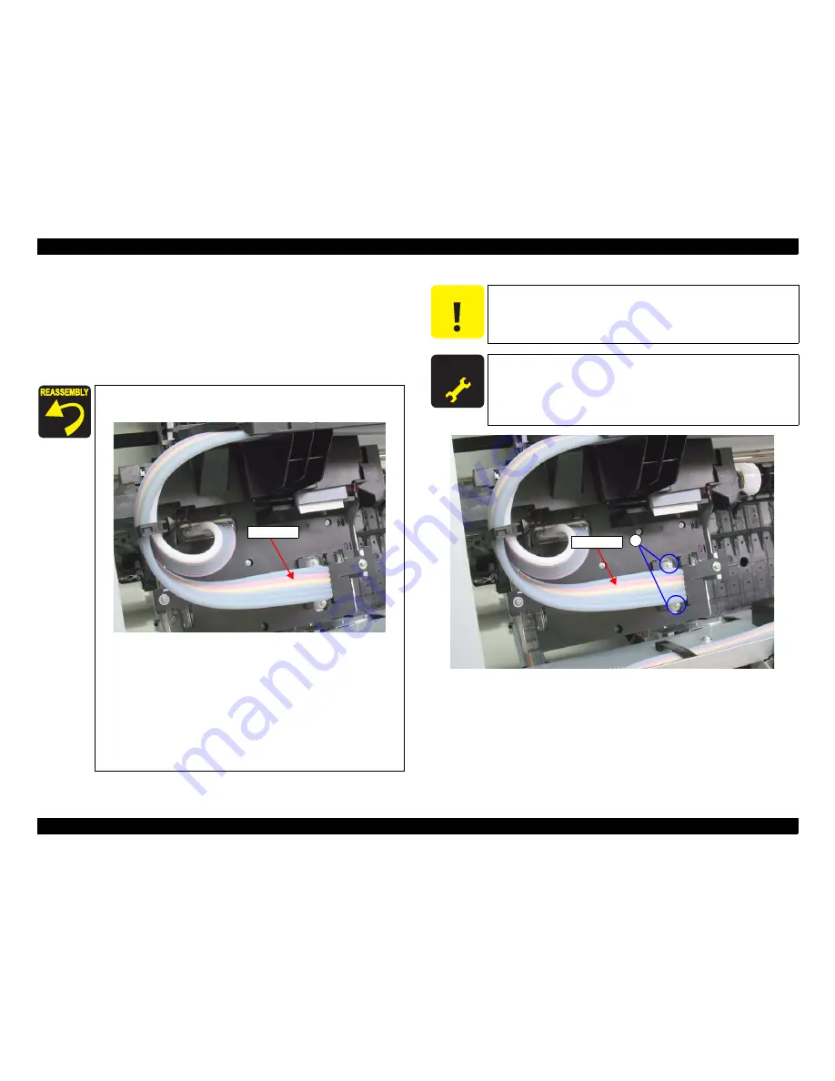
15. Remove the two screws that secure the Ink Tube L, and remove the Ink Tube L.
A) Silver, Phillips, Bind machine screw M2x16 (bit: No.1): two pieces
Figure 4-169. Removing the Ink Tube L
When connecting the Ink Tube L, make sure to connect it
correctly as shown in the figure below.
Use a torque driver with the torque given below when
tightening the screws securing the Ink Tube.
3
±
0.5kgf
⋅
cm
Make sure to install the SEAL RUBBER, JOINT, ASP. The
SEAL RUBBER, JOINT, ASP (1518317) is not included in the
Ink Cartridge Holder and the Ink Tube; therefore, re-use the
originally installed one. Make sure to confirm there is no
damage or no foreign material attached on the sealing rubber
or the joint section visually then. Installing a damaged part
such as mentioned above may cause ink leakage.
Ink Tube L
C A U T I O N
When replacing the Ink Tube L with a new one, make sure to
replace the Ink Tube R together.
A D J U S T M E N T
R E Q U I R E D
Be sure to refer to Chapter 5 “Adjustment”
(see p351)
and perform
specified adjustments after replacing or removing the Ink Tube L.
<Adjustment Item>
1. Counter Clear (Ink Tube)
2. Air Leak Check for Ink Supply Sys.
A
Ink Tube L
Summary of Contents for Stylus Pro 7890 Series
Page 15: ...Confidential C H A P T E R 1 PRODUCTDESCRIPTION ...
Page 94: ...Confidential C H A P T E R 2 OPERATINGPRINCIPLES ...
Page 105: ...Confidential C H A P T E R 3 TROUBLESHOOTING ...
Page 166: ...Confidential C H A P T E R 4 DISASSEMBLY ASSEMBLY ...
Page 351: ...Confidential C H A P T E R 5 ADJUSTMENT ...
Page 444: ...Confidential C H A P T E R 6 MAINTENANCE ...
Page 459: ...Confidential C H A P T E R 7 EpsonStylusPro7700M 7710M CopyMode ...


