


EPSON Stylus COLOR 3000
Rev. A
3-25
WORK POINT
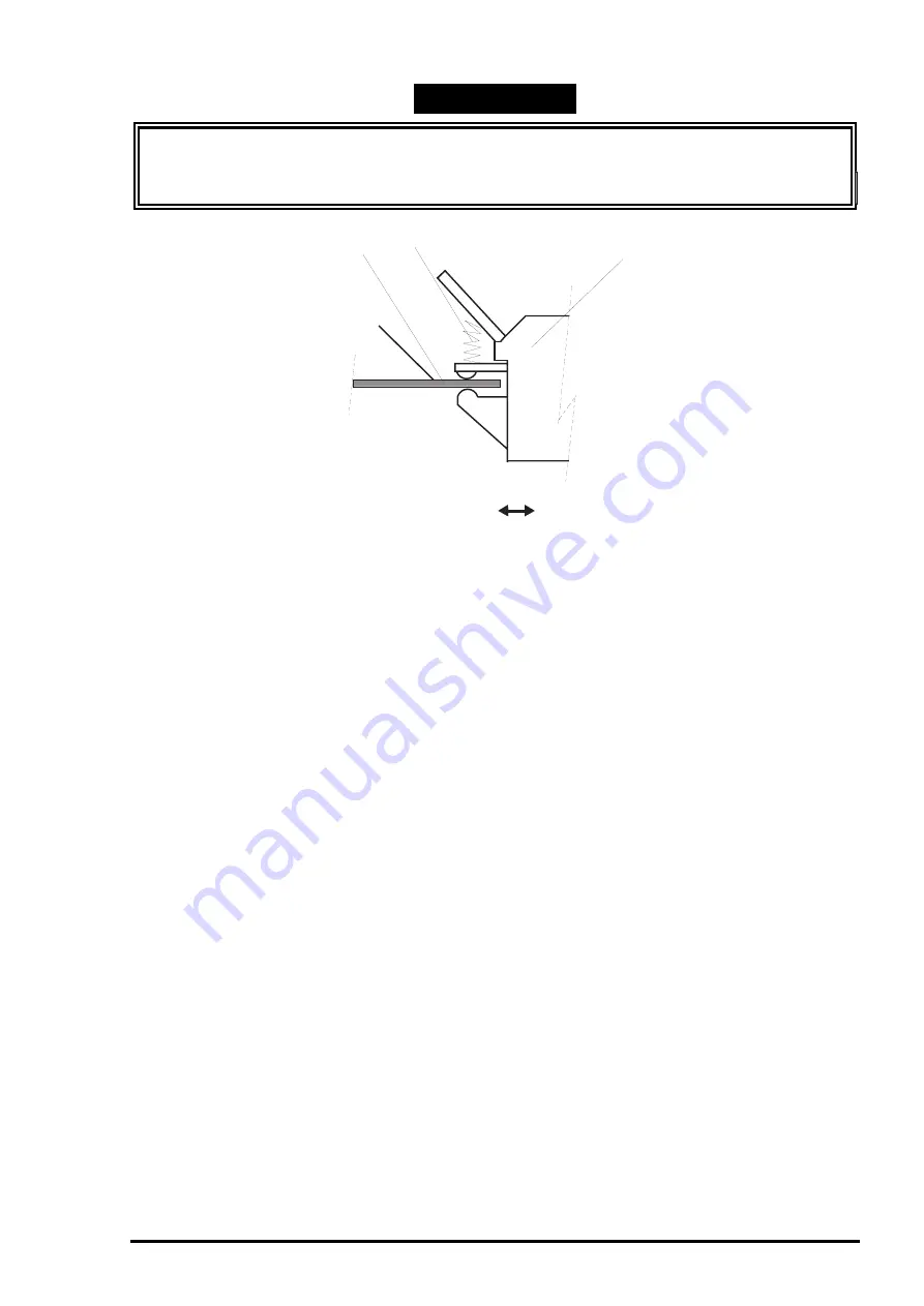
When installing the edge guide unit to the printer mechanism unit, engage the edge guide
unit with the main bottom frame, as shown in Figure 3-22.
Be sure to fix the flange nuts with the specified adhesive. (See Chapter 6.)
Bottom Main Frame
Edge Guide Unit
Spring
Front
Rear
Figure 3-22.
Joining the Edge Guide Frame and Bottom Main Frame
Summary of Contents for Stylus COLOR 3000
Page 5: ......
Page 126: ......
Page 127: ......
Page 150: ...EPSON Stylus COLOR 3000 Rev A 6 5 1 1 1 2 3 4 4 4 4 4 4 Figure 6 1 Lubrication Points 1 ...
Page 151: ...Maintenance Rev A 6 6 9 9 9 9 9 9 9 9 6 7 Figure 6 2 Lubrication Points 2 ...
Page 161: ...EPSON Stylus COLOR 3000 Rev A A 8 ...
Page 162: ...Appendix Rev A A 9 A 2 Circuit Diagrams Figure A 2 C203 MAIN B Board Circuit Diagram 1 2 ...
Page 163: ...EPSON Stylus COLOR 3000 Rev A A 10 ...
Page 164: ...Appendix Rev A A 11 Figure A 3 C203 MAIN B Board Circuit Diagram 2 2 ...
Page 165: ...EPSON Stylus COLOR 3000 Rev A A 12 ...
Page 170: ...Appendix Rev A A 17 Figure A 8 C203 MAIN B Board Component Layout 2 ...
Page 171: ...EPSON Stylus COLOR 3000 Rev A A 18 Figure A 9 C203 PNL Board Component Layout ...
Page 172: ...Appendix Rev A A 19 Figure A 10 C172 PSB Board Component Layout ...
Page 173: ...EPSON Stylus COLOR 3000 Rev A A 20 Figure A 11 C172 PSE Board Component Layout ...
Page 174: ...Appendix Rev A A 21 A 4 Exploded Diagrams Figure A 12 Stylus 3000 Exploded Diagram 1 ...
Page 175: ...EPSON Stylus COLOR 3000 Rev A A 22 Figure A 13 Stylus 3000 Exploded Diagram 2 ...
Page 176: ...Appendix Rev A A 23 Figure A 14 Stylus Color 3000 Exploded Diagram 3 ...
Page 177: ...EPSON Stylus COLOR 3000 Rev A A 24 Figure A 15 Stylus Color 3000 Exploded Diagram 4 ...
Page 180: ...EPSON SEIKO EPSON CORPORATION ...