EPSON Perfection 4490 Photo
Revision B
6
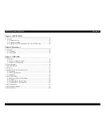
Contents
Chapter 1 PRODUCT DESCRIPTION
1.1 Features.................................................................................................................. 9
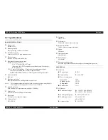
1.2 Specifications ...................................................................................................... 10
1.3 Detailed Specifications........................................................................................ 12
1.4 Interface............................................................................................................... 12
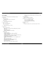
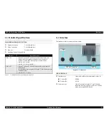
1.5 Exterior Specifications ........................................................................................ 13
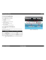
1.5.1 Explanation of Switches ............................................................................. 13
1.5.2 Explanation of LED Indicators................................................................... 13
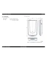
1.5.3 Dimensions ................................................................................................. 14
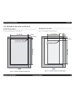
1.5.4 Maximum Document Size and Placement.................................................. 15
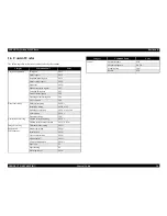
1.6 Control Codes...................................................................................................... 16
1.7 Error-Time Processing......................................................................................... 17
Chapter 2 OPERATING PRINCIPLES
2.1 Engine Operation Outline.................................................................................... 19
2.1.1 Carriage Unit outline .................................................................................. 19
2.1.2 TPU Carriage Unit Outline......................................................................... 20
2.1.3 Carriage Moving Mechanism Operation .................................................... 21
2.1.4 TPU Carriage Drive Mechanism Operation ............................................... 22
2.2 Digital ICE Function Operation .......................................................................... 23
2.2.1 Digital ICE for Film Overview................................................................... 23
2.3 Operation Principle of Electric Circuit................................................................ 24
Chapter 3 TROUBLESHOOTING
3.1 Overview ............................................................................................................. 26
3.1.1 Self-Diagnosing .......................................................................................... 26
3.2 Troubleshooting................................................................................................... 27
Chapter 4 Disassembly / Assembly
4.1 Overview ............................................................................................................. 30
4.1.1 Precautions.................................................................................................. 30
4.1.2 Recommended Tools .................................................................................. 30
4.1.3 Recommended Screws................................................................................ 30
4.2 Disassembly Procedure ....................................................................................... 31
4.2.1 Removing the TPU Unit ............................................................................. 32
4.2.2 Removing the Upper Housing .................................................................... 33
4.2.3 Removing the Carriage Unit....................................................................... 34
4.2.4 Removing the Panel Board ......................................................................... 36
4.2.5 Removing the Main Board ......................................................................... 37
4.2.6 Removing the Power Switch ...................................................................... 40
4.2.7 Removing the Panel FFC............................................................................ 41
4.2.8 Removing the Driven Pulley, Driven Pulley Spring, and the Driven Pulley
Holder Assy. .............................................................................................. 42
4.2.9 Removing the CR Motor Unit, Motor Tension Belt, and the CR Tension
Belt ............................................................................................................ 43
4.2.10 Removing TPU Lower Housing ............................................................... 45
4.2.11 Removing the Sensor Board ..................................................................... 46
4.2.12 Removing the Hinge Assy........................................................................ 46
4.2.13 Removing the TPU Unit Cable................................................................. 47
4.2.14 Removing the DRV Board ....................................................................... 48
4.2.15 Removing Torsion Spring ........................................................................ 49
4.2.16 Removing the TPU Carriage Unit ............................................................ 50
4.2.17 Removing the TPU Inverter Board........................................................... 51
4.2.18 Removing the SUB_C Board, SUB_D Board, and the Lamp .................. 53
4.2.19 Removing the TPU CR Motor.................................................................. 55
Summary of Contents for Perfection 4490 Photo
Page 8: ...C H A P T E R 1 PRODUCTDESCRIPTION ...
Page 18: ...C H A P T E R 2 OPERATINGPRINCIPLES ...
Page 25: ...C H A P T E R 3 TROUBLESHOOTING ...
Page 29: ...C H A P T E R 4 DISASSEMBLY ASSEMBLY ...
Page 57: ...C H A P T E R 5 ADJUSTMENT ...
Page 59: ...C H A P T E R 6 MAINTENANCE ...
Page 63: ...C H A P T E R 7 APPENDIX ...
Page 66: ...Model GT X750 Perfection 4490 Photo Board Main Board Rev A Sheet 1 1 ...
Page 68: ...Model GT X750 Perfection 4490 Photo Board DRV Board Assy Rev A Sheet 1 1 ...
Page 69: ...Model GT X750 Perfection 4490 Photo Board Image Sensor Board Rev B Sheet 1 1 ...
Page 70: ...Model GT X750 Perfection 4490 Photo Board SUB Board Rev A Sheet 1 1 ...
Page 71: ...Model GT X750 Perfection 4490 Photo Board SUB C Board Rev A Sheet 1 1 ...
Page 72: ...Model GT X750 Perfection 4490 Photo Board SUB D Board Rev A Sheet 1 1 ...
Page 74: ...GT X750 Perfection 4490 Photo NO 1 Rev 02 B176 ACCE 0012 10 20 30 40 400 401 ...
Page 76: ...R ev 01 B176 CAS E 002 GT X750 Perfection 4490 Photo NO 3 110 111 101 102 ...


