


Setup & Operation 2. Specifications
34
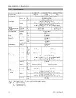
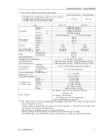
G10 / G20 Rev.20
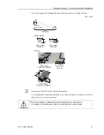
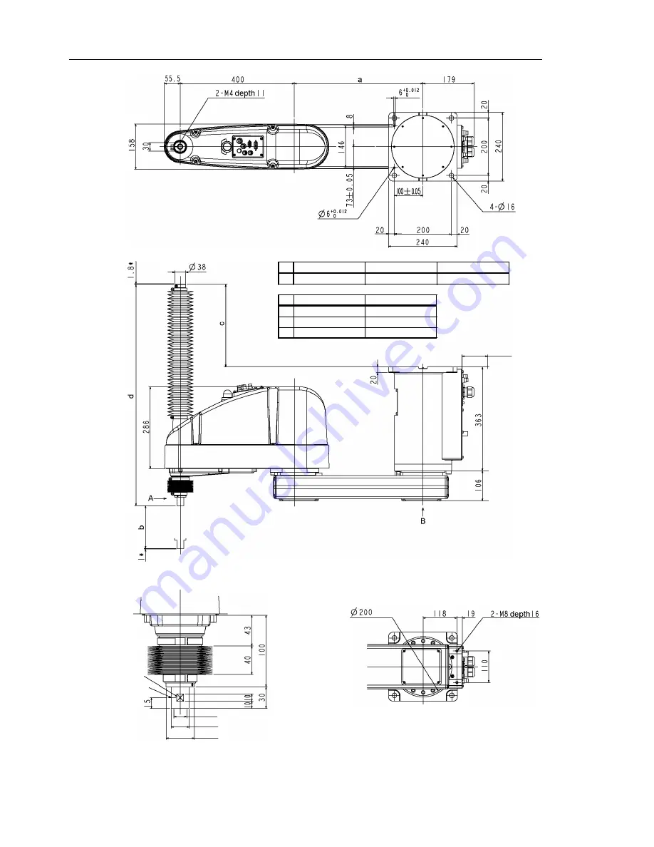
G10-65*CR
G10/G20-85*CR
G20-A0*CR
a
250
450
600
G10/G20-**1CR G10/G20-**4CR
b
150
390
c
29.5
288.5
d
515
774
(Tolerance
applies to
the pin hole)
Conical hole ø4,90°
1 mm flat cut
Max.ø18 through hole
ø25 h7 shaft diameter
90 or more
Space for cables
(*) indicates the stroke margin by mechanical stop.
Detail of “A”
(Calibration point position of Joints #3 and #4)
ø39.5 mechanical stop diameter
Detail of “B”
Summary of Contents for G10 Series
Page 1: ...Rev 20 EM183R3619F SCARA ROBOT G10 G20 series MANIPULATOR MANUAL ...
Page 2: ...MANIPULATOR MANUAL G10 G20 series Rev 20 ...
Page 8: ...vi G10 G20 Rev 20 ...
Page 14: ......
Page 102: ...Setup Operation 5 Motion Range 90 G10 G20 Rev 20 ...
Page 104: ......