Maintenance 14. Calibration
232
G10 / G20 Rev.20
Calibration Using Right / Left Arm Orientations
(1)
Check the point data for calibration
Use a pose (point) you can easily verify the accuracy within the work envelop of
both right and left arm. Then, check the number of pose (point) you want to use.
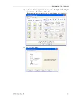
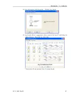
(2) Open the Tools menu | Robot Manager | Control Panel and click the MOTOR ON.
(3) Click the <Free All> button to free all joints from servo control. Now, you can move
arms by hands.
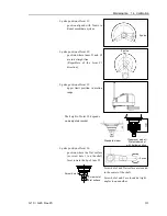
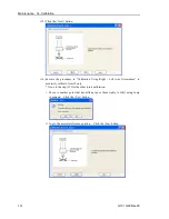
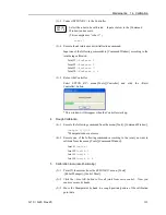
(4) Move the arms to the position of point data for calibration in rightly arm orientation.
(5) From the current position, teach any point data number unused.
This pose (point) is now called P1.
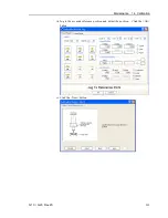
Specify the point number “1” and click the <Teach> button in the [Jog & Teach].
(6) Click the Lock All in the [Control Panel] to lock all joints under servo control.
(7) Switch to the lefty arm orientation. Then, move the arm to the same point.
>Jump P1/L:Z(0) '
Change the arm orientation from righty to lefty
Z is the maximum position
* If there is interference on the way from right to lefty, click the Free All in the
[Control Panel] and change the arm orientation to lefty by hands. Then, go to the
step (6), (7).
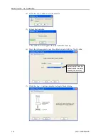
(8) The joints are slightly out of position.
Adjust the gap with the
−
Z in the Jogging group in the [Jog & Teach]. Then, teach
another point data number unused. This pose (point) is now called P2.
Specify point number “P2” and click the <Teach> button in [Jog & Teach].
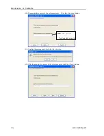
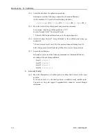
(9) Input the new Hofs value.
>Hofs Hofs (1), Hofs (2) + (Ppls(P1,2) + Ppls(P2,2)) / 2,
Hofs(3), Hofs(4)
(10) From the current lefty arm orientation (the position in the step (8)), teach the point
data number used in the step (8). This pose (point) is called P2.
Specify point number “P2” and click the <Teach> button in [Jog & Teach].
(11) Switch to the righty arm orientation. Then, make sure the manipulator move to the
correct position.
>Jump P2/R
'
Change the arm orientation from lefty to righty
* If there is any interference on the way from lefty to righty, click the Free All in the
[Control Panel] and change the arm orientation to righty by hands. Then, go to
the step (6), (11).
(12) Move the manipulator to other point data and make sure it moves to the correct
position. Teach some more points if required.
* Delete the two points taught for the Joint #2 calibration.
Summary of Contents for G10 Series
Page 1: ...Rev 20 EM183R3619F SCARA ROBOT G10 G20 series MANIPULATOR MANUAL ...
Page 2: ...MANIPULATOR MANUAL G10 G20 series Rev 20 ...
Page 8: ...vi G10 G20 Rev 20 ...
Page 14: ......
Page 102: ...Setup Operation 5 Motion Range 90 G10 G20 Rev 20 ...
Page 104: ......

