

Maintenance 8. Arm #4
172
G10 / G20 Rev.20
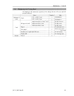
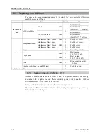
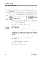
8.1.2 Replacing the Joint #4 Motor: G20
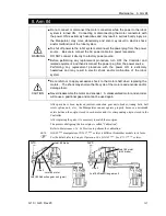
A brake is mounted on the motor of Joints #3 and #4 to prevent the shaft from moving
down due to the weight of the end effector while the power to the Controller is OFF or
while the motor is in OFF status (MOTOR OFF).
Note that the brake will not work during the replacement procedure.
Move the shaft down to its lower limit before starting the replacement procedure by
following the removal steps.
Joint #4 motor
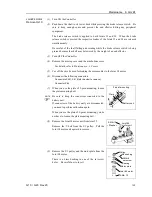
Removal: G20
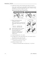
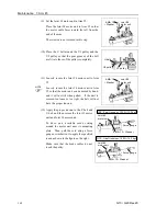
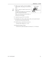
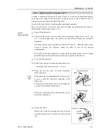
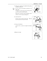
(1) Turn ON the Controller.
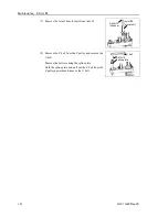
(2) Push down the shaft to its lower limit while pressing the brake release switch. Be
sure to keep enough space and prevent the end effector hitting any peripheral
equipment.
The brake release switch is applied to both Joints #3 and #4. When the brake
release switch is pressed, the respective brakes of the Joints #3 and #4 are released
simultaneously.
Be careful of the shaft falling and rotating while the brake release switch is being
pressed because the shaft may be lowered by the weight of an end effector.
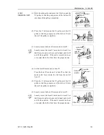
(3) Turn OFF the Controller.
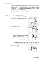
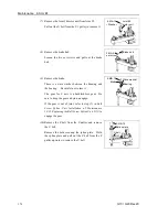
(4) Remove the arm top cover and the arm bottom cover.
For details, refer to
Maintenance: 3. Covers
.
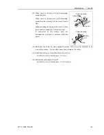
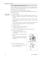
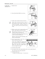
(5) Cut off the wire tie used for binding the motor cables to the Joint #4 motor.
(6) Disconnect the following connectors.
Connectors X241, X41 (Hold the claw to remove.)
Connector X64
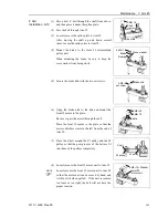
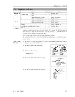
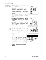
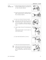
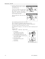
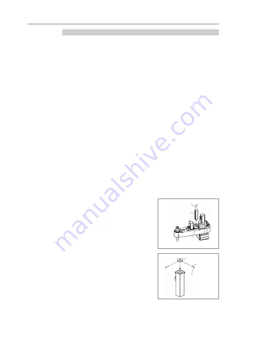
(7) Remove the Joint #4 motor from the reduction
gear unit.
Unscrew the reduction gear unit bolts securing
the Joint #4 motor shaft and bolts securing the
Joint #4 motor.
2-M4
×
10
Joint #4 motor
Reduction
gear unit
M3
×
10
(Securing the motor shaft)
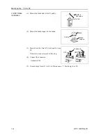
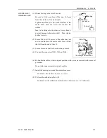
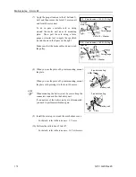
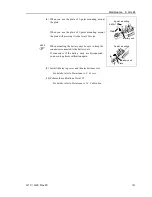
(8) Remove the ring from the Joint #4 motor.
There is a brass bushing in the both set screw
holes. Be careful not to lose it.
Bushing
Ring
2-M3
×
8
set screw
Summary of Contents for G10 Series
Page 1: ...Rev 20 EM183R3619F SCARA ROBOT G10 G20 series MANIPULATOR MANUAL ...
Page 2: ...MANIPULATOR MANUAL G10 G20 series Rev 20 ...
Page 8: ...vi G10 G20 Rev 20 ...
Page 14: ......
Page 102: ...Setup Operation 5 Motion Range 90 G10 G20 Rev 20 ...
Page 104: ......