background image


Milling programming: 

Once the milling tool is installed in the machine, the robot welding gun and the milling process 

are as follows: 


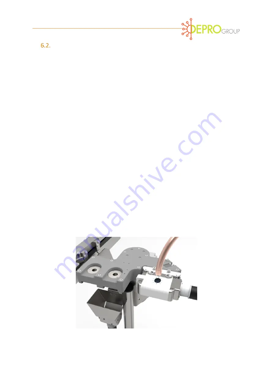
The welding electrodes are adjusted linearly to each other and to milling device as in 

the welding position (figure 10). When using a C-guns at least one electrode should be 

90 degrees to the electrode cutter. 


The closing force for milling with Quattro blade tools is 1.5 kN (337.2 lbf) and single 

cutting tools is 1 kN (224.8 lbf) (basic setting). Based on this value, the milling result 

(material removal) can be optimized later. 


The  milling  time  is  approx.  2  seconds.  This  value  also  can  be  changed  later  when 

optimizing. 


The milling tool should rotate before closing and after opening the welding gun. A lead 

time of two seconds before and five seconds afterwards is recommended. During the 

post milling process, chips are removed by blow-off and transported into the collection 

container.  Depending  on  the  extent  of  the  milled  contaminants,  the  post  milling 

process can be increased up to ten seconds to accommodate additional blow-off. 


During the milling operation the welding current must be disengaged as it can damage 

the tool. 


Figure 10 Position of the electrodes to the milling tool 


Summary of Contents for Combi Machine

Page 1: ...Version 1 0 April 2021 Combi Machine User Manual ...

Page 2: ...n instructions 9 Process flow welding milling exchanging 10 General process flow 10 Milling sub process 12 Exchange or replacement sub process 13 Programming 14 Alignment 14 Milling programming 15 Programming electrode extractor 16 Orientation and grease access 17 Programming electrode replacement 18 Exchange and changing of the electrode cartridges 19 Testing electrodes and adapters 19 Optimizati...

Page 3: ... 22 Gun pressures that can impact performance 23 Troubleshooting 23 Maintenance 32 Inspection of magazine cartridges 2 3 days 32 Inspection of changing canisters monthly 32 Care of the milling tools 32 Overview of maintenance intervals 33 Contact 34 ...

Page 4: ...milling tool of the machine must not be handled manually Electrode caps milling devices for hand welding guns must be used according to the service instructions No work pieces or materials other than spot welding electrodes according to ISO 5821 CuCrZr CuZr CuCr may be used Personal protective equipment to be used as required For correct use of the machine please review the entire operating manual...

Page 5: ... horizontal configuration The Combi machine is made up of several subcomponents as indicated by Figure 1 Cleaning of the milling tools from excess electrode material takes place during and after milling Removed electrodes are collected in separate integrated collection container Optional Used electrodes and milling debris can be collected in separate waste container depending on container configur...

Page 6: ...on galvanized steel sheets is being used more often Through the welding process there is a formation of contaminant material buildup of zinc layers on the electrode work surfaces resulting in an increase of resistance to the work area resulting in a loss of energy at the electrode working surface which is needed for heating the weld metal This result in a lack of repetitiveness of the expected wel...

Page 7: ...ed personnel electricians Operating without a protective cover removed is not recommended and protective eyewear is recommended Gloves are recommended when working with chips or debris from the machinery Be aware of pinch points on the unit Stay away from electric drive when in operation or under power General instructions for device configuration Devices are modular so they can be quickly and eas...

Page 8: ...caps The milling tool consist of a holder and cutter or blade that is held in place with a set screw Figure 4 Some tools come with Blue rings that must be snapped in place to ensure a proper fit Other holders come without a ring and equally provide enough protection so that debris does not enter the housing Before the first use of the electrode milling tool the selection of the tool must be checke...

Page 9: ...e the ring is snapped in place to the holder Alternate holders are available without the blue ring Figure 10 Ensure there are no collisions with welding parts robots or other moving elements in the welding area As a check the entire workflow should be simulated All machine connections including cables hoses and pipelines should be laid so that they do not cause a tripping hazard Laying cables and ...

Page 10: ...LED has a continuous signal delivered with the correct milling speed Process flow welding milling exchanging General process flow The process Flow consists of several steps each of which is set up and optimized for the number of spot welds before each milling process which depends wear caused by the welding task In general electrodes are to be reshaped after 50 200 weld spots based on optimum runn...

Page 11: ...Figure 6 General process flow ...

Page 12: ...t MONITORING ROTATION Make sure that complete signal exchange is operating correctly before determining the spatial coordinates on the welding robot in accordance with the following sections This includes the ability to limit the duration of milling with closed welding guns using several rotation pulses Figure 7 Sub process milling ...

Page 13: ...lacement sub process The sub process EXCHANGING Figure 5 3 1 has the output signals e g output EXCHANGING and status feedback for example input LEVEL OF CAP CARTRIDGE as identified below Figure 8 Sub Process exchange ...

Page 14: ...ectrode A extraction 2 extractor 3 Sensing electrode is absent 1 cap detector 4 Replace Gun Electrode A 3 magazine cartridge 1 5 Sensing Gun Electrode A is present 1 cap detector 6 Check Gun Electrode B presence 1 cap detector 7 Gun Electrode B extraction 2 extractor 8 Sensing Gun Electrode B is absent 1 cap detector 9 Replace Gun Electrode B 4 Magazine Cartridge 2 10 Sensing Gun Electrode B is pr...

Page 15: ...g result material removal can be optimized later The milling time is approx 2 seconds This value also can be changed later when optimizing The milling tool should rotate before closing and after opening the welding gun A lead time of two seconds before and five seconds afterwards is recommended During the post milling process chips are removed by blow off and transported into the collection contai...

Page 16: ...se increased wear and tear or even damage to machine and to electrode holder Figure 11 Position of the removal tool The electrodes are inserted all the way to the upper edge but the removing tool is not in contact with electrode holder The welding guns always remain sufficiently open when changing The time to loosen the electrode in the jaws of the extractor is less than one second A longer stay i...

Page 17: ... the electrode caps fall into the waste container the approach of the weld gun must always be in one direction from above Figure 12 The gun should be turned 180 degrees in order to remove the electrode from the opposite arm to again have the electrode fall from the extractor into the waste container In the vertical orientation there is a grease access hole below the extractor unit that would typic...

Page 18: ...ure 14 Welding guns with inclined electrode holders may need to compensate on the approach to the new electrode Attention incorrect position of electrodes in the extraction tool may lead to an increase wear or even damage of the machine and electrode holder or adapter The welding gun closing force should not exceed 100 kg when pressing on the new electrode cap Ensure the welding gun is sufficientl...

Page 19: ...turn in opposite directions Rotate the caps to load the new electrodes For use with welding guns with different electrode geometries can differing cartridges to match the gun requirements Figure 15 Magazine with cartridges Testing electrodes and adapters The presence or absence of the electrodes in the process steps identified in Section 6 1 are confirmed by the inductive query as follows When ele...

Page 20: ...e 3 6 4 Electrode shape ISO or similar 5 Electrode material CuCrZr CuZr CuCr 160 Hb 15 6 Welding assignment sheet coating 0 5 7 0mm 7 Items of each part 20 150 Values refer to electrode ø16mm type F16 ISO5821 Different parameters are possible in varying cases however it can lead to significant limitations of the milling results the electrode service life as well as increased tool and equipment wea...

Page 21: ... inaccurate program can severely affect the milling result weld quality and the electrode life In the case of an offset milled electrode the milling tool can quickly reach the electrodes cooling channel resulting in an electrode failure Possible form of offset are shown in Figure 16 Position the welding gun and electrodes so that The active surface of both electrodes is center Replace distorted el...

Page 22: ...cker chips are produced causing increased wear and risk of clogging Perfect geometry of the welding electrodes without residues on the surface can be achieved by removing only 100 150 μm resulting in improved service life The following figure shows a penetration depth of the zinc oxide layer of 140 μm after 400 welds Frequent removing of a small amount of material for example every 50 150 welds ge...

Page 23: ...electrodes or no removal of the electrodes no signal of the rotation display no running noise of the device No power supply depending on device type 230 575 V AC 50 60 Hz available Check current supply on the device input and check terminal box if there is current flow No power supply to the drive control signal to the motor from the PLC is not triggered Check programming of the PLC or the signal ...

Page 24: ...ctor 2 No milling of electrodes or no removal of the electrodes no signal of the rotation display however running noise of the device is present There is no milling tool or extraction tool used A correct milling tool or extraction tool is to be installed The bayonet mount of the milling tools or extractor tool is defective The tool holder is to be tested by checking if traction is provided to the ...

Page 25: ...ect in power supply The phase change must be made in the feed ensuring correct rotation even when later replacing the drive or device Milling tool or extraction tool is damaged or dull Exchange affected tool Welding gun has low closing pressure during milling The removal of the cap must be Check closing pressure and adjust if necessary The devices are supplied in the following variations 3a Simple...

Page 26: ... for milling Check closing pressure and adjust if necessary 3c No or little material removed when milling on the electrode Signal of the speed evaluation is 3 LED with speed evaluation not available Milling tool does not rotate or too slow because there are errors according to items 1 and 2 Review solutions described in points 1 and 2 The device does not run with full power in three phases audible...

Page 27: ...hortened Incorrect milling parameters lead to excessive material removal Minimize material removal per milling Reduce milling time and gun arm closing pressure during milling Minimize electrode wear between the cuts Reduce welding currents and clamp closing pressure during welding The electrode wear cannot be reduced without risk for spot weld quality should be milled more frequently Adhesive and ...

Page 28: ...gh during the first run of the device Cutting speed too low due to low power or transmission Please refer to 1 3 Closing force of the welding guns too low Gradually increase closing pressure Milling time too low Gradually increase milling time 6 Electrodes not suitably milled Please refer to 5 Please refer to 5 Milling insert clogged Clean milling insert Please refer to 4 Milling insert no longer ...

Page 29: ...ctly positioned in the extraction tool with the cap retracting too far into the extraction tool causing the electrode holder sleeve or adapter to come in contact with the extraction tool Check the position of the caps Both caps must be aligned exactly collinear with the axis of rotation to the extraction tool Do not drive one or both caps too far into the extraction tool 9 Electrodes cannot be dri...

Page 30: ...ap 11 Electrode effective area is too small and or not round Wrong milling insert Check part replace if necessary Swinging the milling cutter through unstable assembly and or too long milling Ensure secured correctly to the stand or swivel Shorten the milling time 12 Mill tool forms chatter marks on the electrode Wrong milling tool Check part replace if necessary The welding gun does not close ove...

Page 31: ...and correct if necessary 15 With flat electrodes ISO Form A or C the effective surface is not milled cleanly During welding the active surface has funnel shaped deformation It has built up a strong diffusion layer Therefore gradually increase the milling time and the closing pressure Check whether the required welding spot diameter can be achieved with a smaller effective surface diameter Check wh...

Page 32: ...ded that the system be programmed so that after the last welding cycle electrodes are milled before being replaced The maintenance staff can review the milling performance after the electrode exchange to determine whether the blade of the milling tool requires replacement Inspection of changing canisters monthly It is recommended that every 2 4 weeks the collection canisters have be emptied on the...

Page 33: ... sharpening coatings may be compromised reducing life cycle Overview of maintenance intervals Table 5 Interval Module part Measure 1 100 or shift change Electrodes Visual inspection of the milling result If the caps are not milled correctly replace the tool 2 3 000 5 000 milling cycles or monthly Reservoirs Tool Milling unit with chip disposal Visual inspection of the milling tool If the caps are ...

Page 34: ...ontact Depro group www deprogroup com enquiries deprogroup com Depro Global Offices Hampshire UK Columbus Ohio USA Tokyo Japan Mira India Ulsan South Korea Bovisio Masciago Italy Rep of Chuvashia Russia ...

Reviews: