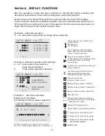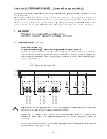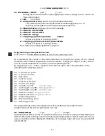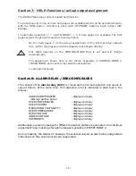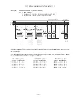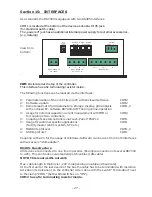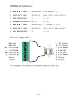
=== PROGRAM-MODE ===
3 I-CONVERTER PRIM [1000 ] A / X
( 5 ... 13000) A
Selects the primary current of the current converter.
Sequential adjustment of L1...L3.
via the
é
/
ê
keys. Save and continue with ENTER
4 I-CONVERTER SEC 1000 A /[ 5 ]A
( 1 / 5 A )
This sets the secondary current of the current converter.
Selection via
é
/
ê
. Save and continue with ENTER
5 END STOPP
Programming of the maximum number of active
capacitor branches.
Depending on the selected operation mode the
maximum number of connected capacitors at the output
groups L1…L3 and (if available) for the output groups
Σ
(three-phase capacitors) are set.
The visible symbols of the capacitors correspond to the
connected outputs.
Input via
é
/
ê
. Save and continue with ENTER
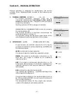
6 CONTROL SERIES
[1]
( 1...20 + ED )
The ratio of the capacitor branch powers determines the
control series, the power of the first capacitor always
being assigned the value 1.
Selection of desired control series consecutively for
L1…L3 and for
Σ
(three-phase outputs).
If the required control series should not be present, the
user may define a special one in control series “ED” ( see
Annex 4: Control-series editor )
7 CONTROL PRINCIPLE
The control preference may be selected here:
SEQUENTIAL connection
LOOP connection
INTELLIGENT loop connection (default setting)
COMBINED CHOKE
See Section 13 for an explanation of the control modes.
Selection with
é
/
ê
keys.
Save and continue with ENTER
8 POWER 1st STAGE [0.01 ... 255.99] / [10...2550] kvar
To determine the controller's response sensitivity, the
dimensions of the smallest capacitor (stage 1) must be
known. They are entered in two steps in kvar. The
integral kvar values (before the comma) are initially
selected via the
é
/
ê
keys and saved with ENTER.
The positions after the comma are then selected, again
via the
é
/
ê
keys.
If the capacitor value is below the response sensitivity, a
warning will occur ( indication of “!” in the display )
- 14 -
7 CONTR.PRINCIPLE
[ INTELLIGENT ]
PROGRAM-MODE
3 I-CONVERTER PRIM
[ 1000]A / 5 A
1000]A / 5 A
1000]A / 5 A
L1
L2
L3
8 POWER 1.STAGE
[ 25].00 kvar
25 .00 kvar
25 .00 kvar
L1-N
L2-N
L3-N
6 CONTR.SERIES L1-N
12333
12333
12333
[ 3]
3
3
L1-N
L2-N
L3-N
1 2 3 4 5
5 END STOP L1-N
[ 5]
5
5
L1-N
L2-N
L3-N
1 2 3 4 5
PROGRAMM-MODE [5]
PROGRAM-MODE [1]
PROGRAM-MODE [3]
PROGRAM-MODE

