Section 5: DISPLAY OF GRID PARAMETERS
5.1 Display of 3 selected grid parameters
In Auto-Mode, button
é
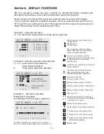
leads to display mode 1. Here 3 (free selectable) grid parameters
are displayed in large letters. The selection and storage of these values is done in the
Display- Editor.
Example: Display mode 1:
Desired values selected in the
Display Editor (see section 13 )
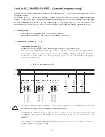
5.2 Display of particular grid parameters (from AUTO-MODE by pressing ENTER)
By repeated activation of the “ENTER”-button (in automatic operation) several grid
parameters can be displayed (s. table below):
Action Display
Unit
in% Bargraph 3-phase
possible
ENTER 1 LINE VOLTAGE
V
x
ENTER 2 CURRENT
A (apparent-, active-, reactive)
x
ENTER 3 REACTIVE POWER
kvar
x
ENTER 4 ACTIVE POWER
kW
x
ENTER 5 APPARENT POWER
kVA
x
ENTER 6 DIFF. kvar to target
kvar
x
ENTER 7 FREQUENCY
Hz
ENTER 8 TEMPERATURE
°C / °F
ENTER 9 3.-31. HARMONICS
V/ I
x
x
x
ENTER 10 HARMONICS THD-V/I
x
x
x
ENTER 11 Comp.- power
(only at real capacitor current measurement)
ENTER 12 ENERGY
kvarh / kWh (+), (-)
ENTER 13 TIME / DATE
é
/
ê
change the date format
ENTER 14 Software version
é
/
ê
more information
ENTER return to: 1
Buttons
é
/
ê
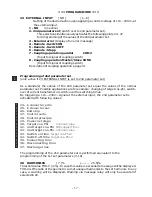
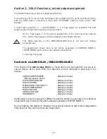
change the display format:
The values can be displayed in their unit, in % or as bar chart.
Examples, see next page.
- 9 -
14
137
140
kvar
kW
kVA
Q
P
S

