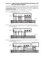
Section 4: DISPLAY - FUNCTIONS
After the operating voltage has been switched on, the BR7000 briefly indicates with
description and software-version before changing to automatic operation.
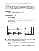
Actual values and symbols of the particular operation state are shown in the display.
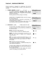
In the automatic operation (standard) capacitor steps are automatically switched on or
off to reach the pre-set target cos-phi. This happens when the required reactive power is
higher than the value of the smallest capacitor step.
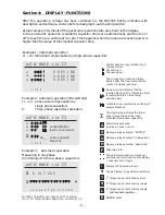
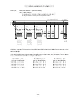
Example 1: Automatic operation
L1...L3: Individual compensation by single-phase capacitors
- 8 -
Number of switching outputs until end stop.
Here: 15 three-phase capacitors, end-stop: 15
Control direction is symbolized by a
compact arrow:
Connecting-in
Connecting-out
The connecting-in arrow is always
located after the maximum possible
number of stages (end stop)
An open arrow indicates that the
required blocking time (Discharge time)
is running before an impending
switching step
A double arrow symbolizes switching of
several branches
The sigma-sign indicates the three-
phase-value (mean-value) resp.
activated three-phase-capacitors
Alarm relay activated
(declines in case of error)
Message relay activated: “SUPPLY”
Message relay activated:“Undercurrent”
Message relay aktivated: “Harmonics”
FAN-relay: ON
The particular capacitor outputs are
permanently monitored. Inverse display
= capacitor out of range
Display of 2nd parameter-set
Supply display (i.e.generator operation)
nd
2 Target-cos phi activated by timer
nd
2 Target-cos phi activated by supply
nd
2 Target-cos phi activated by supply
a
ERROR COM
nd low load operation
S
A
U
H
F
2
T
L
E
é
é
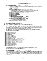
Example 2: Automatic operation (Mixed Mode)
L1...L3: phase wise compensation by
single phase capacitors
Σ:
Three-phase capacitors activated
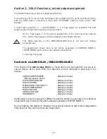
Example 3: Automatic operation
Measuring in one phase
Controlling of 15 three-phase-capacitors
Σ
0.869 IND
0.869 IND
0.869 IND
0.917 CAP
L1
L2
L3
1 2 3 4
Σ
Σ
Σ
AUTO-MODE cos
ϕ
AUTO-MODE cos
ϕ
AUTO-MODE cos
ϕ
L1
L2
L3
1 2 3 4
1 2 3 4 5 6 7 8 9 10 11 12 13 14 15
control direction
(here: connected-in)
active capacitor
branches

