82
REV. 07/2019
HYDRAULIC SYSTEM
7
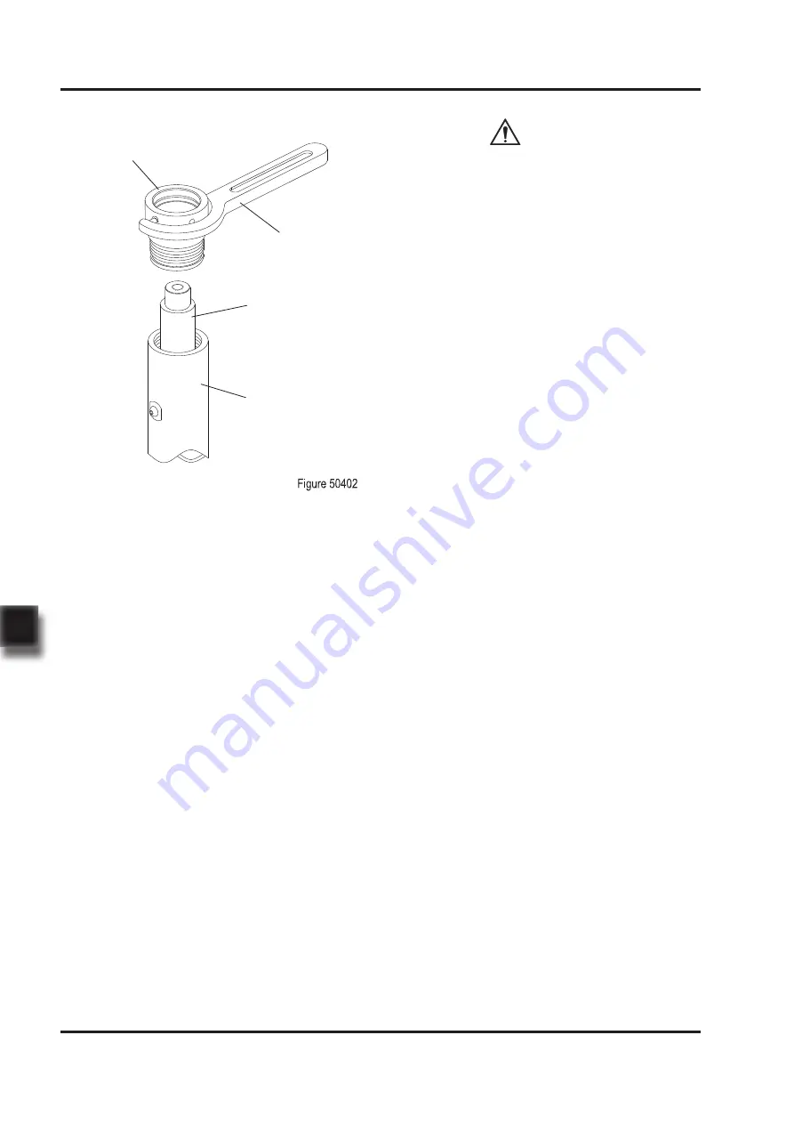
Cylinder Cap
Cylinder Wrenches
Piston Rod
Cylinder Tube
*
See Appendix A - Service Manual - Mast for
the removal of lift cylinder.
-
-
-
O-ring is quite flexible and easy to install,
but it must not be pulled up to the extent of
permanent deformation, nor scroll it while
installing;
Y-ring or X-ring needs to be identified if it is
for shaft or hole to avoid misplacement;
The removed O-rings and dust rings should
be replaced with new ones.
-
-
Cylinder parts must not be arbitrarily repla-
ced, the original products provided by the
manufacturer should be used;
After maintenance and assembly of the cylin-
der is completed, pressure leak testing must
be carried out before it can be put operation
once again.
Before the testing, discharge the air within
the cylinder, run the cylinder in a small range
of movement for several times, and pay
attention if it is moving without blocking and if
there is uneven resistance during the moving.
Upon the pressure testing, raise the pressure
slowly and observe carefully for leaks.
-
-
7.6.2 Cylinder Installation Precautions
All parts should be cleaned up before asse-
mbly, then to be assembled after being
dried;(during assembly, apply appropriate
amount of hydraulic oil for lubrication)
The tools used to install the seals must
be made of soft metal or suitable plastic,
without burrs and sharp edges on surfaces.
It is prohibited to use the tools that can
easily damage the surface of seals, such as,
screwdriver or other similar tools with hard
front edges.
Where the hydraulic seals to be installed
should be free of burrs, sharp edges and
cracks. If the installation of seals needs to
cross sharp edges, grooves or cuts, protective
devices must be used for protection. Before
installing, lubrication should be performed to
the seals and the mounting positions first with
hydraulic oil.
*
See Appendix A - Service Manual - Mast for
the installation of lift cylinder.
CAUTION
Summary of Contents for LIST JX0
Page 1: ...Service Manual JX0 Task Support Vehicle...
Page 2: ...Service Manual Task Support Vehicle JX0...
Page 14: ...1 1 1 INFORMATION SPECIFICATIONS...
Page 15: ...2 NOTE...
Page 23: ...10 2 2 MAINTENANCE...
Page 24: ...11 NOTE...
Page 34: ...21 3 3 STRUCTURE FUNCTIONS...
Page 35: ...22 NOTE...
Page 45: ...32 4 4 CHASSIS SYSTEM...
Page 46: ...33 NOTE...
Page 50: ...37 5 5 DRIVE SYSTEM...
Page 51: ...38 NOTE...
Page 68: ...55 6 6 OPERATING SYSTEM...
Page 69: ...56 NOTE...
Page 83: ...70 7 7 HYDRAULIC SYSTEM...
Page 84: ...71 NOTE...
Page 86: ...73 REV 07 2019 HYDRAULIC SYSTEM 7 7 1 1 Hydraulic Schematic Diagram...
Page 99: ...86 8 8 ELECTRICAL SYSTEM...
Page 100: ...87 NOTE...
Page 130: ...REV 07 2019 ELECTRICAL SYSTEM 8 117 operational...
Page 169: ...REV 07 2019 ELECTRICAL SYSTEM 8 156 8 16 Electrical Schematic Diagrams...
Page 170: ...REV 07 2019 ELECTRICAL SYSTEM 8 157...
Page 172: ...REV 07 2019 ELECTRICAL SYSTEM 8 159...
Page 173: ...160 9 9 TROUBLESHOOTING...
Page 174: ...161 NOTE...
Page 179: ...166 APPENDIX...
Page 180: ...167 NOTE...
Page 181: ...168 A A SERVICE MANUAL MAST...
Page 182: ...169 NOTE...
Page 185: ...172 REV 07 2019 SERVICE MANUAL MAST A...
Page 187: ...174 REV 07 2019 SERVICE MANUAL MAST A...
Page 190: ...177 B B SERVICE MANUAL BATTERY...
Page 191: ...178 NOTE...
Page 204: ...191 C C SCHEDULE...
Page 205: ...192 NOTE...