


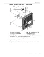


Mounting the Switch
Enterasys D-Series Hardware Installation Guide 2-15
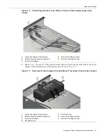
8.
Plug
the
DC
power
cord
from
the
power
supply
into
the
switch
DC
power
receptacle
that
is
appropriate
for
your
type
of
power
supply.
•
For
the
D2
‐
PWR
supply,
plug
into
the
PWR1
‐
A
or
PWR2
‐
A
receptacle.
•
For
the
D2
‐
PWR
‐
POE
supply,
plug
into
the
PWR1
‐
B
or
PWR2
‐
B
receptacle.
•
For
the
D2
‐
HIPWR
‐
POE
power
combiner,
see
“
Connecting
a
D2
‐
HIPWR
‐
POE
Power
Combiner
”
on
page 2
‐
25.
9.
Plug
the
AC
cord
into
the
power
supply’s
AC
receptacle.
10. (Optional)
Use
the
wire
ties
provided
to
secure
the
power
cords
inside
the
wall
mounting
tray.
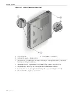
11. Using
appropriate
screws
and
the
screw
holes
in
each
corner
edge
of
the
wall
mounting
tray,
attach
the
assembled
kit
to
your
desired
wall
location.
Secure
the
assembled
unit
in
place
by
positioning
the
screw
holes
over
the
installed
wall
screws
and
pulling
slightly
downward
on
the
unit.
12. Attach
network
cables.
Refer
to
“
Connecting
to
the
Network
”
on
page 2
‐
28
for
more
information.
13. Plug
each
AC
power
cord
into
a
dedicated,
grounded
AC
outlet.
See
“
Connecting
Power
to
the
Switch
”
on
page 2
‐
26
for
information
on
redundancy
and
the
initialization
process.
14. (Optional)
If
you
have
purchased
an
optional
plastic
cover,
attach
it
to
the
mounted
D2
switch
as
described
in
“
Installing
the
Optional
Plastic
Cover
”
(page 2
‐
33).
Installing the Switch in the Lockbox and Mounting on a Wall
To
assemble
the
switch
and
other
components
in
the
D2
lockbox,
proceed
as
described
in
the
following
sections:
•
Installing
the
Switch
in
the
Lockbox
•
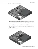
Install
your
power
supplies,
following
the
steps
in
either
“
Installing
Power
Supplies
”
(page 2
‐
16)
or
“
Installing
the
D2
‐
HIPWR
‐
POE
in
the
Lockbox
”
(page 2
‐
18)
•
“
Connecting
Network
Cabling
and
Attaching
the
Wire
Relief
Bracket
”
(page 2
‐
21)
•
“
Mounting
the
Lockbox
on
the
Wall
”
(page 2
‐
22)
•
“
Attaching
and
Locking
the
Cover
”
(page 2
‐
23)
•
“
Removing
the
Lockbox
Cover
”
(page 2
‐
25)
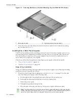
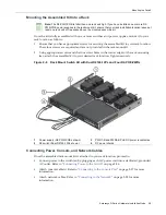
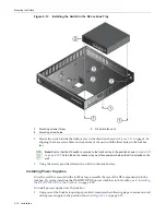
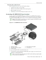
Installing the Switch in the Lockbox
To
install
the
switch
in
the
lockbox
tray,
proceed
as
follows:
1.
Detach
the
lockbox
key
and
place
it
in
a
secure
location
for
later
use.
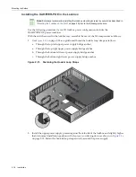
Note:
Once assembled, the serial number on the bottom of your D2 switch will be accessible
through the window on the bottom of the wall mounting tray. In the event you need to view it, you will
need to detach the wall mounting tray from the wall and (if installed) remove the power supply from
underneath the serial number window.
Summary of Contents for D2G124-12
Page 2: ......
Page 12: ...x ...
Page 16: ...xiv ...
Page 20: ...Getting Help xviii About This Guide ...
Page 26: ...PoE Power over Ethernet Support 1 6 Introduction ...
Page 66: ...Resetting the D2 HIPWR POE 3 4 Troubleshooting ...
Page 74: ...Regulatory Compliance A 8 Specifications ...
Page 76: ...Index 2 ...


