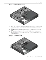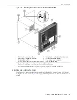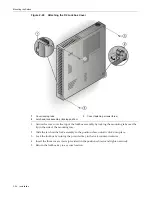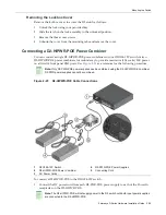
Installing the Optional Plastic Cover
Enterasys D-Series Hardware Installation Guide 2-33
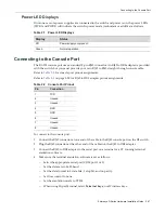
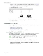
Figure 2-26 Cable Connection (LC shown) to Uplink Port with SFP Installed
3.
Plug
the
other
end
of
the
cable
into
the
appropriate
port
on
the
other
device.
Some
cables
may
be
terminated
at
the
other
end
with
two
separate
connectors,
one
for
each
fiber
‐
optic
strand.
In
this
case,
ensure
that
the
transmit
fiber
‐
optic
strand
from
the
D2
is
connected
to
the
receive
port
of
the
other
device,
and
the
receive
fiber
‐
optic
strand
on
the
D2
is
connected
to
the
transmit
port
of
the
other
device.
4.
Repeat
this
procedure
for
other
SFP
ports,
if
needed.
5.
If
an
SFP
port
is
unused,
install
a
dust
cover.
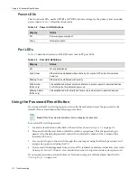
Installing the Optional Plastic Cover
If
you
have
purchased
a
D2
‐
COVER
‐
W
optional
plastic
cover,
you
can
install
it
over
a
freestanding
or
wall
‐
mounted
switch
as
shown
in
Figure 2
‐
27
on
page 2
‐
34.
1
Combo SFP port with MGBIC installed
2
LC cable connector
3
Release tab
Note:
The optional plastic cover can be installed over a freestanding unit or a unit mounted in a
D2-WALL-MNT kit. It is not intended for use in a D2 lockbox.
Summary of Contents for D2G124-12
Page 2: ......
Page 12: ...x ...
Page 16: ...xiv ...
Page 20: ...Getting Help xviii About This Guide ...
Page 26: ...PoE Power over Ethernet Support 1 6 Introduction ...
Page 66: ...Resetting the D2 HIPWR POE 3 4 Troubleshooting ...
Page 74: ...Regulatory Compliance A 8 Specifications ...
Page 76: ...Index 2 ...

