148
dataPAC User’s Guide
Chapter 4 - Off Route Analysis with the dataPAC
Mode
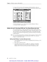
Press <SELECT> to toggle between Start-Up and Coast-Down. This changes the Speed
field to reflect the beginning or end ranges for machine speed.
Speed (RPM)
Depending on whether you have selected Start-Up or Coast-Down, this lets you specify the
beginning and ending RPM for the data set sampling. No data collection occurs outside of
these limits.
Press <SELECT> while in the Speed (RPM) box to display the Speed (RPM) window.
Use the arrow keys to select either Minimum or Maximum. Press <SELECT> to open an
edit window to adjust the speed displayed. Press <DONE> when complete.
If Trigger Type is set to “None,” this parameter has no effect.
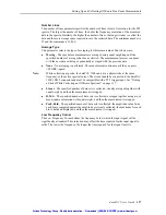
Meas. Variable
The Measurement Variable parameter allows you to choose how to measure the signal
coming from the transducer. For example, if you have a velocity sensor, you can measure
either velocity or displacement.
Press <SELECT> while in the Meas. Variable box to open the Measurement Variable
window. Use the arrow keys to move in the list. Press <SELECT> to select the variable.
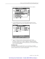
Unit Text
Press <SELECT> while in the Unit Text box to select the display units for this
measurement.
The selections depends upon the current selection in the Measurement Variable parameter.
Note that this simply specifies the text that is used to label the measurement. The scaling for
the measured data is automatically set based upon the selected Unit Text.
z
RMS - Root Mean Square amplitude is the amplitude of a sine wave at the frequency of
interest.
z
Pk - Peak Amplitude is the RMS Amplitude multiplied by the square root of 2. This is
the peak (0 to maximum) amplitude of a sine wave at the frequency of interest and is
calculated from the RMS value.
z
PP - Peak to Peak Amplitude is the RMS Amplitude multiplied by the square root of 2
times 2. This is the peak-to-peak (minimum to maximum) amplitude of a sine wave at
the frequency of interest and is calculated from the RMS value.
Use the arrow keys to move in the list. Press <SELECT> to select the Unit Text.
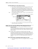
Hardware Range
Hardware Range allows you to specify the detectable range when acquiring the signal. Press
<SELECT> key and the Hardware Range dialog box opens.
Press <SELECT> to display a list of Hardware Range values. Use the arrow keys to select a
value. This parameter is used to control the hardware range when taking a measurement.
Measurement starts at the specified range. Anything over the specified value is not stored (it
is clipped).
Artisan Technology Group - Quality Instrumentation ... Guaranteed | (888) 88-SOURCE | www.artisantg.com
Artisan Technology Group - Quality Instrumentation ... Guaranteed | (888) 88-SOURCE | www.artisantg.com

