


www.enlogic.com
42
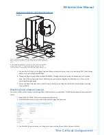
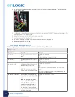
Temperature & Humidity Sensor Installation Instructions
EA9102, EA9103, & EA9105
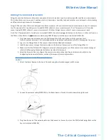
1. Secure the sensor box to the perforated rack enclosure door by threading a cable tie through the recessed channel
in the sensor box and through the door.
Note: There are two recessed channels on the back of the sensor box which also includes a magnet to help secure
the sensor.
2. Secure the RJ45 cable along the desired path to the PDU using the remaining cable ties.
3. For the 3 Temperature & 1 Humidity sensor (model EA9105) only: Secure the two additional temperature probes
near the top and the bottom of the perforated rack enclosure door using the cable ties.
4. Use the RJ45 Quick Disconnect Coupler and an Ethernet cable to extend the length of the sensor input cable and/or
to serve as an easy disconnect point for rack door removal. Refer to the EN Series User Manual for instructions on
how to create custom cord lengths using the RJ45 Quick Disconnect Coupler.
Note: Use either the 1.8m Ethernet cable included with the Enlogic sensor or any other CAT5 or CAT6 Ethernet cable
with a standard RJ45 plug.
5. Plug the sensor cable (or the connected Ethernet cable) into the Sensor 1 or Sensor 2 port on the PDU/Inline
Energy Meter or the Sensor Hub (model EA9106). It may take 1-3 minutes (depending on the model and
configuration) for the PDU recognize the sensor.
Note: Only plug the 3 Temperature & 1 Humidity sensor (model EA9105) directly into the Sensor 1 or Sensor 2 port.
It is not recommended to plug this sensor into the Sensor Hub (model EA9106).
6. The Enlogic sensor is now installed and ready for use.
Sensor Input Hub Installation Instructions
EA9106
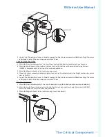
1. Secure the sensor box to the perforated rack enclosure door by threading a cable tie through the recessed channel
in the sensor box and through the door.
Note: There are two recessed channels on the back of the sensor box which also includes a magnet to help secure
the sensor.
2. Secure the RJ45 cable along the desired path to the PDU using the remaining cable ties.
3. For the 3 Temperature & 1 Humidity sensor (model EA9105) only: Secure the two additional temperature probes
near the top and the bottom of the perforated rack enclosure door using the cable ties.
4. Use the RJ45 Quick Disconnect Coupler and an Ethernet cable to extend the length of the sensor input cable and/or
to serve as an easy disconnect point for rack door removal. Refer to the EN Series User Manual for instructions on
how to create custom cord lengths using the RJ45 Quick Disconnect Coupler.
Note: Use either the 1.8m Ethernet cable included with the Enlogic sensor or any other CAT5 or CAT6 Ethernet cable
with a standard RJ45 plug.
5. Plug the sensor cable (or the connected Ethernet cable) into the Sensor 1 or Sensor 2 port on the PDU/Inline
Energy Meter or the Sensor Hub (model EA9106).
Note: Only plug the 3 Temperature & 1 Humidity sensor (model EA9105) directly into the Sensor 1 or Sensor 2 port.
It is not recommended to plug this sensor into the Sensor Hub (model EA9106).
Door Switch Sensor Installation Instructions
EA9109
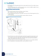
Top Door Mounting Option
1. Attach the Door Switch assembly to the top of the rack using the Adhesive backed mount and cable ties.
2. Attach the Switch Sensor to the top corner of the rack (on the side that the rack door will close) using double-sided
tape. Secure the cable to the top of the rack using cable ties.
3. Attach the Magnetic Sensor to the rack door using double-sided tape.
4. Thread the sensor connection cable through the rack. Secure the cable with cable ties. Plug the cable into a sensor
port on the PDU.