background image

29


IMPORTANT!


LISEZ


ET


SUIVEZ


TOUTES


LES


INSTRUCTIONS


POUR


L’INSTALLATION


ET


L’ENTRETIEN,


NOTAMMENT


CELLES


PORTANT


SUR


LE


NETTOYAGE


DE


L’APPAREIL


À


EFFECTUER


SELON


LES


DIRECTIVES


ET


CELLES


PORTANT


SUR


LE


REMPLACEMENT


DES


JOINTS


(ANNUELLEMENT)


ET


DES


PIÈCES


(AU


BESOIN).


ENGLAND’S


STOVE


WORKS


N’EST


PAS


RESPONSABLE


DES


DOMMAGES


NI


DES


BLESSURES,


QUELS


QU’ILS


SOIENT,


SUBIS


EN


RAISON


DE


NÉGLIGENCE


OU


À


CAUSE


D’UNE


INSTALLATION


OU


D’UNE


UTILISATION


DANGEREUSE


DE


CE


PRODUIT.


POUR


TOUTE


QUESTION,


COMMUNIQUEZ


AVEC


LE


SERVICE


DE


SOUTIEN


TECHNIQUE.


ENTRETIEN


ANNUEL


Nettoyage


du


ventilateur


d’évacuation


Même


si


le


ventilateur


d’évacuation


et


son


boîtier


ont


été


conçus


de


façon


à


réduire


l’accumulation


de


cendres,


une


certaine


quantité


de


cendres


s’y


accumulera


pendant


toute


la


saison


de


chauffage.


La


quantité


et


le


type


de


cendres


dépendent


du


type


de


granules


et


du


système


de


ventilation,


mais,


en


général,


il


y


a


peu


d’accumulation.


Si


vous


trouvez


une


grande


quantité


de


cendres


volantes


dans


le


ventilateur


d’évacuation


lors


de


son


nettoyage,


vous


devez


en


effectuer


l’entretien


tous


les


mois


ou


deux


fois


par


mois


pour


éviter


une


accumulation


excessive.


Instructions


Avant


de


procéder


à


l’entretien


du


ventilateur


d’évacuation,


assurez

vous


que


l’appareil


est


débranché


et


complètement


refroidi.


Retirez


le


panneau


latéral


gauche


du


poêle


à


l’aide


d’un


tournevis


à


douille


ou


d’une


clé


de


5/16


po.


Dégagez


légèrement


le


système


de


ventilation


du


ventilateur


d’évacuation


de


façon


à


pouvoir


retirer


celui

ci


du


poêle.


Une


fois


le


panneau


enlevé,


vous


verrez


clairement


le


ventilateur


d’évacuation.


Débranchez


les


deux


fils


qui


relient


le


faisceau


de


câblage


du


poêle


au


ventilateur


d’évacuation


à


l’aide


des


embouts


à


raccord


rapide.


Débranchez


le


capteur


de


chaleur


qui


est


fixé


à


l’aide


d’une


vis


sur


le


ventilateur


d’évacuation.


Dévissez


les


cinq


(5)


vis


autotaraudeuses


de


5/16


po


qui


fixent


le


ventilateur


d’évacuation


au


tube


d’évacuation.


Soulevez


le


ventilateur


d’évacuation


et


retirez

le


du


poêle.


Le


joint


qui


scelle


le


ventilateur


d’évacuation


au


tuyau


d’évacuation


est


fragile,


alors


soyez


très


prudent


lorsque


vous


retirez


le


ventilateur.


Cependant,


même


en


étant


prudent,


il


est


facile


de


déchirer


ce


joint


fragile


et,


comme


l’étanchéité


est


essentielle


à


cet


endroit,


il


est


préférable


de


remplacer


le


joint


(pièce


 ‐ 

PU

CBMG)


chaque


fois


que


vous


enlevez


le


ventilateur


d’évacuation.


Après


avoir


enlevé


le


ventilateur


d’évacuation,


nettoyez


toute


accumulation


de


cendres


dans


le


tuyau


d’évacuation


à


l’aide


d’un


aspirateur


eau


et


poussière.


Utilisez


un


pinceau


doux


pour


retirer


soigneusement


toute


accumulation


de


cendres


à


l’intérieur


du


ventilateur


d’évacuation


et


sur


sa


pale.


Inspectez


le


moteur


du


ventilateur


d’évacuation


pour


trouver


toute


accumulation


de


poussière


et


enlevez

la


soigneusement,


en


vous


assurant


que


tous


les


trous


de


refroidissement


du


moteur


sont


dégagés


et


libres


de


dépôts


de


poussière.


Réinstallez


le


ventilateur


en


suivant


à


l’inverse


les


étapes


décrites


précédemment.


N’oubliez


pas


de


vérifier


l’état


du


joint


du


ventilateur


d’évacuation


et


de


fixer


le


capteur


de


chaleur


au


ventilateur


d’évacuation.


Réinstallez


le


système


de


ventilation


et


les


panneaux.


Nettoyage


du


ventilateur


de


convection


Comme


toujours,


assurez

vous


que


le


poêle


est


refroidi


et


débranché


avant


d’effectuer


l’entretien


d’un


de


ses


composants,


quel


qu’il


soit.


Comme


le


ventilateur


de


convection


ne


traite


pas


les


sous

produits


de


combustion,


il


ne


nécessite


pas


un


nettoyage


aussi


minutieux


que


le


ventilateur


d’évacuation.


Cependant,


la


poussière


de


la


maison


et


d’autres


débris


présents


dans


l’air


peuvent


s’accumuler


sur


les


pales


du


ventilateur


de


convection.


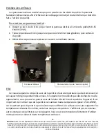
Ventilateur


d’évacuation


Ventilateur


de


convection


Summary of Contents for 25-CBPAH

Page 1: ...ING OR FIRE OFFICIALS ABOUT RESTRICTIONS AND INSTALLATION INSPECTION REQUIREMENTS INCLUDING PERMITS IN YOUR AREA Manufactured By England s Stove Works Inc PO Box 206 Monroe VA 24574 Rev 12 2019 SAVE THESE INSTRUCTIONS INSTALLATION OPERATION MANUAL 25 CBPAH 55 SHPCBPAH 55 TRPCBPAH THIS WOOD HEATER NEEDS PERIODIC INSPECTION AND REPAIR FOR PROPER OPERATION CONSULT THE OWNER S MANUAL FOR FURTHER INFOR...

Page 2: ...ting or otherwise operate this wood heater in a manner inconsistent with operating instructions in this manual Mobile Home Use This freestanding pellet unit is approved for mobile home or doublewide installation with the outside combustion air hook up See the Installation section of this manual for details pertaining to mobile home installations Mobile home installation must be in accordance with ...

Page 3: ...n 14 Vent Termination Clearances 15 Outside Air Hookup 16 Floor Protection 17 Daily Operation Getting Started 18 Lighting a Fire 18 Daily Operation Notes 19 Control Board Control Board Settings 20 Error Codes 21 Power Failure 22 Maintenance Daily Important Notes 23 Daily Ash Removal 23 Cleaning the Burn Pot 24 Weekly Baffle Removal 25 Clean Out Covers 25 Monthly Important Notes 26 Venting Pipe Cle...

Page 4: ...it into the two installation holes and lean forward on the front wall of the stove The bend in the bar should bend toward the front door opening and not backward toward the burn pot Installation Holes Air Wash Channels Fire Box Install the Air Wash Bar tabs into the holes and not into the air wash channels The bend of the air wash bar should face TOWARD the front door Front Door Opening Air Wash B...

Page 5: ...y always able to walk you through any installation issues repairs problems or other questions that you may have Wishing you years of efficient quality and comfy heating Everyone at England s Stove Works Please Note While information obtained from our web site and through our Technical Support line is always free of charge there will be a service charge incurred with any on site repairs or maintena...

Page 6: ...mission standards using pellet fuel U S Test Standard US EPA 40 CFR Part 60 Subpart 60 536 Particulate Emissions 0 763 grams hr CO Emissions 0 013 grams min Efficiency 77 6 HHV Tested To UL 1482 00 ASTM E 1509 ULC ORD C1482 M1990 ULC S627 00 Notes for this unit Product may vary slightly from diagram Clearances are the minimum for this unit and may need to be increased in the rear to have proper ve...

Page 7: ...es and will take the path of least resistance while it is still hot 3 Exhaust Location Outside walls are generally the best place to install a stove since they allow easy exhaust and intake air installation using our Dura Vent AC 3000 Kit AC 33000 if Canada If there is not a feasible way to install the stove on an outside wall there are methods for venting the stove up through the roof but they te...

Page 8: ...le in operation Keep children away Supervise children in the same room as this appliance Alert children and adults to the hazards of high temperatures Do NOT operate with protective barriers open or removed Keep clothing furniture draperies and other combustibles away Installation MUST comply with local regional state and national codes and regulations Consult local building fire officials or auth...

Page 9: ...n Venting Guidelines WARNING INSTALL VENT AT CLEARANCES SPECIFIED BY THE VENT MANUFACTURER ALWAYS install vent pipe in strict adherence with the instructions and clearances included with your venting system DO NOT connect this pellet stove to a chimney flue which also serves another appliance DO NOT install a flue pipe damper or any other restrictive device in the exhaust venting system of this un...

Page 10: ...inal of a mechanical draft system other than direct vent appliances sealed combustion system appliances shall be located in accordance with the following a Not less than 3 ft 91 m above any forced air inlet located within 10 ft 3 0m b Not less than 4 ft 1 2 m below 4 ft 1 2 m horizontally from or 1 ft 305 mm above any door window or gravity air inlet into any building c Not less than 2 ft 0 61 m f...

Page 11: ... appliance collar to the exhaust blower output using three sheet metal screws Secure the pellet vent to the outside of the house using a wall strap just below the 90 degree elbow Seal each pipe connection joint with high temperature RTV Silicone to ensure the system is leak free Check with the specific venting system manufacturer s instructions before doing so If the pellet vent pipe being used is...

Page 12: ...ust output of the pellet stove and attach the appliance collar to the exhaust blower output using three sheet metal screws Seal each pipe connection joint with high temperature RTV Silicone to ensure the system is leak free Check with the specific pipe manufacturer s instructions before doing so If the pellet vent pipe being used is not a Twist Lock system three 3 sheet metal screws are required a...

Page 13: ...S629 if Canada Connection to any other factory built chimney may result in a poorly operating or dangerous stove installation When connecting to an existing masonry chimney the cross sectional area of the flue must be considered A chimney with a flue larger than 6 round 28 27 sq in may require relining with an approved pellet stove chimney lining system Use an appliance collar where the pellet ven...

Page 14: ... stove MUST be grounded with 8 solid copper grounding wire or equivalent terminated at each end with an NEC approved grounded device Carefully follow all clearances listed in the appropriate section of this manual AND follow the venting manufacturer s minimum clearance requirements Similarly be certain the venting system used is approved for mobile home use Installation must be in accordance with ...

Page 15: ...hrough the roof surface Notes on termination of Pellet Vent Pipe from NFPA 211 2006 ed Section 10 4 Termination 10 4 5 See also INSTALLATION section of manual AND additional notes above Not less than three 3 feet above any forced air inlet located within ten 10 feet Not less than four 4 feet below four 4 feet horizontally from or one 1 foot above any door window or gravity air inlet into any build...

Page 16: ...ollowed The pipe used for outside air hookup must be metal with a minimum thickness of 0209 in 25 gauge mild steel or greater and an inside diameter of approximately 2 0 in All pipe joints and connections should be sealed with pipe clamps or other mechanical means to insure a leak free outside air connection Long runs of pipe and excessive elbows for outside air should be avoided Due to frictional...

Page 17: ...tector can still be used for aesthetic reasons Prefabricated floor protectors which are UL listed ULC if Canada or equivalent can be purchased or a floor protector can be built from standard materials two sheets of 5 thick cement board covered with ceramic tile would be a suitable floor protector which meets the 2 R value requirement When using any floor protector consider that this stove is not o...

Page 18: ...mation on Error Codes can be found in the Error Code section of this manual At this point the dry run is complete and your pellet heating appliance is ready for normal operation Lighting a Fire In order for this stove to operate the hopper must first be filled with pellet fuel Lift the hopper lid using the flush mount handle and pour the pellet fuel directly into the hopper We recommend using only...

Page 19: ...tored at a safe distance from the pellet heater storing fuel in close proximity to the stove can result in a fire Do not install or operate this unit outside in a greenhouse or in any area that is high in moisture This pellet burning room heater is equipped with a specially designed burn pot which comes preinstalled from the factory This burn pot elevates the burning pellets and delivers air at th...

Page 20: ...trol board is now adjusting the heat output to your desired level The blower speed will increase the same amount as the heat range because the stove is designed to operate with the blower speed greater than or equal to the heat range Pressing the Down arrow will decrease the heat range and blower speed To increase the blower speed without increasing the heat range press the Blower Speed Up arrow u...

Page 21: ...hough the stove may have ignited the pellets the control board did not register a high enough temperature to determine the fire was lit If a fire was ignited wait for the unit to cool clean the burnpot and restart the unit E 3 This error code indicates the preset maximum allowable exhaust temperature was exceeded Commonly referred to as Over Firing the E 3 code means something in the stove is caus...

Page 22: ... OFF If the power is interrupted for more than approximately three minutes the unit will be OFF when power returns IMPORTANT Do NOT open the hopper lid or the door to the unit during power outage Open the closest outside door and a window to reduce the chance of any combustion byproducts entering the home from the stove Wait for the power to be restored and then press the ON button to restart the ...

Page 23: ...Carefully monitor the ash build up in the stove when first operating the unit as well as whenever a different brand of pellets is burned While the amount of ashes generated by this unit is not excessive compared to a traditional log burning woodstove keeping the unit clean and free of ash is ESSENTIAL for peak performance and maximum efficiency Ash build up hampers airflow reduces efficiency and c...

Page 24: ...ing ashes from the stove cleaning the burn pot is the other essential part of daily maintenance that will keep the stove operating at its peak Pellets contain varying amounts of impurities and fusible material that will accumulate in the burn pot over time Some pellets will contain much higher amounts of these fusible impurities therefore extra vigilance may be required to maintain a clean burn po...

Page 25: ...top baffle inside the firebox above the door by lifting it up and pulling it forward then tilting it sideways to remove it from the stove The part number for the top baffle is AC PAHTB Remove any ash that has accumulated behind the baffle in the stove The use of a utility vacuum is highly recommended because it will prevent fly ash from falling through the exhaust holes and into the exhaust chambe...

Page 26: ...an remain HOT long after the fire has gone out and EVEN after the Shut Down cycle is complete Always use extreme caution when handling potentially hot stove parts even if you think they should be cold Monthly maintenance should include the steps listed in this section AS WELL AS the steps listed in the Daily Maintenance and Weekly Maintenance section Intervals between monthly cleanings will depend...

Page 27: ...n on the stove to the vertical transition will accumulate fly ash and should be inspected carefully and brushed clean Check the termination cap to be certain it is not clogged or restricted by any fly ash accumulation After thoroughly cleaning the venting system reseal any disassembled seams with high temperature silicone Part AC RTV3 if applicable to your venting system Inspect seams that were no...

Page 28: ... season Leaving ash and other build up in the stove during the non heating months can lead to premature metal degradation in the stove and venting system Using extra attention to detail and being certain to be very thorough in the end of season cleaning will help increase the operating life of the stove and venting system The unit should be unplugged during the summer months and periods of non use...

Page 29: ...ive 5 5 16 self drilling screws which hold the exhaust blower to the exhaust blower tube Lift the exhaust blower up and out of the stove The gasket which seals the exhaust blower to the exhaust blower tube is fragile so take extra care when removing the blower Even when being careful though it is easy to tear this fragile gasket and since an airtight seal is crucial here it is best to replace this...

Page 30: ...ew on either side of the auger mounting collar With a utility vacuum in hand let the auger assembly slide out of the auger tube just enough so that the vacuum can be used to remove any fines from this area Reinstall the auger assembly and tighten the two set screws reinstall the back panel being certain to tighten the retaining screws on the rear of the stove Cleaning Pellet Fines Inside Auger Tub...

Page 31: ... or a hose clamp Room blower not operating 1 Loose thermal sensor 1 Tighten connection on sensor 2 Blower speed set higher than heat range causing stove to cool and blower to cycle 2 Lower blower speed 3 Loose connection 3 Check control board connection Exhaust blower not operating 1 Loose connection 1 Check control board connection 2 Bad blower 2 Replace blower 3 Bad vacuum sensor 3 Replace vacuu...

Page 32: ...ellets 3 Check igniter for buildup or failure OT Code on Control Board OverTemp 1 Convection Room Air blower failure 1 Check convection blower for proper function replace if necessary 2 Partially blocked flue 2 Check flue for obstructions 3 Using fuel other than premium wood pellets 3 Use ONLY premium wood pellets in this stove Notes 1 Whenever instructed to check replace the vacuum sensor also ch...

Page 33: ...a 5 16 wrench Before loosening any auger motor bolts detach the wiring harness from the auger motor Locate the auger motor assembly at the rear of the stove and begin by loosening the 2 1 8 allen set screws on either side of the cast iron auger motor coupler Slide the auger assembly out of the tube Remove the 4 screws which hold the cast iron auger motor coupler to the auger motor using a 5 16 wre...

Page 34: ...e beginning any component replacement be certain the unit is unplugged and thoroughly cooled down Remove the rear panel using a 5 16 wrench and locate the convection blower Detach the convection blower from the wiring harness before going any further Loosen and remove the 4 5 16 screws which hold the blower assembly to the stove remove the blower assembly from the stove Installation of the new blo...

Page 35: ...ghly cooled down Remove the left side panel and locate the combustion exhaust blower Disconnect the venting system from the exhaust blower and disconnect the exhaust blower from the stove wiring harness To remove the venting pipe removal of the rear panel using a 5 16 wrench may be necessary Remove all 5 screws which hold the exhaust blower to the exhaust blower tube Remove the heat sensor which i...

Page 36: ...cement be certain the unit is unplugged and thoroughly cooled down Remove the right side panel see pg 43 for panel instructions Removal of the rear panel may help as well Locate the vacuum switch as shown in the diagram below Disconnect the stove wiring harness and vacuum hose from the vacuum switch taking note of where connections were made Remove the 2 screws which hold the vacuum switch to the ...

Page 37: ...t be certain the unit is unplugged and thoroughly cooled down Remove the rear panel of the unit using a 5 16 wrench Locate the igniter as shown in the diagram below Disconnect the igniter wiring from the control board and use a 5 16 wrench to remove the two igniter retaining screws that fasten the assembly to the stove Remove the assembly from the stove Loosen the Allen set screw 1 8 Allen wrench ...

Page 38: ...d latched for twenty four hours to allow the cement to harden See next page for more info 2 Window If you are replacing the window gasket Part AC GGK the new gasket will already have adhesive on one side Remove the paper on the adhesive side and place the gasket around the outside edge of the glass centered over the edge Fold the gasket edges over on the glass forming a U shape 3 Combustion Blower...

Page 39: ...art AC GGK This gasket serves to cushion the glass from the steel door and brackets 6 Reinstall the glass tabs using the screws previously removed Do not over tighten the screws 7 Install the new door gasket Part AC DGKHD using the provided high temperature adhesive 8 Hang the door back on the stove and close tightly and allow 24 hours for adhesive to cure Ceramic Glass Specifications Glass Size 9...

Page 40: ...ntrol board using a 5 16 wrench or nut driver The control board can be removed from the unit by loosening the two outside screws and pulling the board back to the inside of the stove A 6 amp quick blow fuse is used on this Control Board NOTE The bottom three control buttons are preset at the factory and are not user adjustable See the Daily Operation section on page 18 of the manual for more instr...

Page 41: ... ANY DAMAGE OR INJURY INCURRED DUE TO NEGLECT OR DUE TO UNSAFE INSTALLATION OR USAGE OF THIS PRODUCT CALL TECHNICAL SUPPORT WITH ANY QUESTIONS WIRING DIAGRAM Caution Shock Hazard Press the Off button and let the appliance completely cool BEFORE unplugging the appliance and beginning any maintenance or component replacement Risk of shock if appliance is not unplugged before service PU CB19 Control ...

Page 42: ...LID HINGES The hopper lid is attached to the top of the stove by two removable hinges To remove the hopper lid hinges Remove the 4 screws that hold each hinge in place using a 5 16 socket Re Install hinges in the reverse method HOPPER LID HANDLE The hopper lid handle snaps into place in the opening in the hopper lid To remove the hopper lid handle Lift the hopper lid up in the open position Press ...

Page 43: ...OVE the 3 5 16 screws that hold the side panel to rear of the stove Grasp the panel and pull until the panel is removed from the side tracks and comes off of the stove Re install the side panels using the reverse of this method FINISH This new unit has been painted with High Temperature paint that should retain its original look for years If the unit should get wet and rust spots appear the spots ...

Page 44: ...SPECIFIED AND REPLACING GASKETS ANNUALLY AND PARTS AS NEEDED ENGLAND S STOVE WORKS IS NOT RESPONSIBLE FOR ANY DAMAGE OR INJURY INCURRED DUE TO NEGLECT OR DUE TO UNSAFE INSTALLATION OR USAGE OF THIS PRODUCT CALL TECHNICAL SUPPORT WITH ANY QUESTIONS ILLUSTRATED PARTS DIAGRAM Auger Motor Assembly Door Assembly ...

Page 45: ...Switch 15 PU CB19 Control Board Not Shown R WIRE H06 Control Board Wiring Harness Not Shown AC HPS Hinge Pin qty 2 1 AC MBSP Stove Paint Not Shown AC SHN2 3 8 Nickel Spring Handle Not Shown CA AC Auger Coupler 26 CA AMPP Auger Mounting Plate 27 PU AFS Steel Auger 25 AC CHAPAH Igniter Assembly 16 PU HH Hopper Lid Hinge 6 PU VH Vacuum Hose Not Shown AC GGK Glass Gasket Not Shown AC G9 Door Glass 21 ...

Page 46: ...TECHNICAL SUPPORT WITH ANY QUESTIONS CU RG Rubber Vibration Dampener 28 PU RSP Right Side Panel 9 PU LSP Left Side Panel 8 PU SSHL Hopper Lid 19 PU CBAWB Air Wash Bar 3 PU SSRP Rear Panel Not Shown AC CT Cleaning Tool Not shown You may write your unit s Manufacture Date and Serial Number in the blank spaces on this sample tag next page for future reference This sample tag also shows the safety inf...

Page 47: ...NCLUDING CLEANING THE UNIT AS SPECIFIED AND REPLACING GASKETS ANNUALLY AND PARTS AS NEEDED ENGLAND S STOVE WORKS IS NOT RESPONSIBLE FOR ANY DAMAGE OR INJURY INCURRED DUE TO NEGLECT OR DUE TO UNSAFE INSTALLATION OR USAGE OF THIS PRODUCT CALL TECHNICAL SUPPORT WITH ANY QUESTIONS ...

Page 48: ...cracking breakage and welded seam separation 2 Electrical components accessory items glass and the painted surface of the stove are covered for one 1 year from the date of purchase Conditions and Exclusions 1 Damage resulting from over firing will void your warranty 2 This warranty does not apply if damage occurs because of an accident improper handling improper installation improper operation abu...

Page 49: ...ted by the manufacturer The dealer from which the unit was purchased or the factory at our option will perform the warranty service Other Rights This warranty gives you specific legal rights you may also have other rights which may vary from state to state England s Stove Works Inc P O Box 206 Monroe VA 24574 800 245 6489 To submit a Warranty Claim call 800 245 6489 to speak with our Technical Sup...

Page 50: ... to be valid Please send this information within thirty 30 days from the original date of purchase Use any of these three easy ways to send your warranty information in Mailing Address England s Stove Works Inc Technical support Department P O Box 206 Monroe Virginia 24574 Fax Number 434 929 4810 Twenty four hours a day Online Registration To register online visit our warranty registration website...

Page 51: ..._______ V Email Address _______________________________________________ Dealer Information VI Purchased From _____________________________________________ VII Address ___________________________________________________ VIII City_______________________ State________ Zip Code __________ Unit Information IX Model Number_____________________ Purchase Date _____________ X Purchase Price _______________...

Page 52: ......

Page 53: ...CTION DES INSTALLATIONS Y COMPRIS L OBTENTION DE PERMIS PROPRES À VOTRE RÉGION Fabriqué par England s Stove Works Inc PO Box 206 Monroe VA 24574 Rév 12 2019 CONSERVEZ CES INSTRUCTIONS GUIDE D INSTALLATION ET D UTILISATION 25 CBPAH 55 SHPCBPAH 55 TRPCBPAH AFIN D ASSURER LE BON FONCTIONNEMENT DU POÊLE À BOIS VOUS DEVEZ L INSPECTER ET LE RÉPARER PÉRIODIQUEMENT CONSULTEZ LE GUIDE D UTILISATION POUR OB...

Page 54: ...e modifier ce réglage et d utiliser ce poêle à bois d une manière non conforme au mode d emploi indiqué dans le présent guide Utilisation dans une maison mobile L utilisation de ce poêle autoportant est approuvée pour des maisons mobiles ou pour une installation en double largeur avec raccordement à l extérieur pour l air de combustion Consultez la section Installation du présent guide pour connaî...

Page 55: ...nts des terminaisons des évents 15 Raccordement à l air extérieur 16 Protection du sol 17 Utilisation quotidienne Guide de démarrage 18 Allumage d un feu 18 Remarques à propos de l utilisation quotidienne 19 Panneau de commande Réglages du panneau de commande 20 Codes d erreur 21 Panne de courant 22 Entretien Quotidien Remarques importantes 23 Retrait quotidien de la cendre 23 Nettoyage du pot de ...

Page 56: ... trous d installation et pencher dans la direction de la paroi avant du poêle La partie courbée de la barre devrait être orientée vers la porte avant et non vers le pot de combustion Trous d installation Fentes d évacuation d air Foyer Insérez les languettes de la barre d évacuation d air dans les trous et non dans les fentes d évacuation d air La partie courbée de la barre d évacuation d air devr...

Page 57: ...vice de soutien technique au 1 800 245 6489 Nous sommes presque toujours en mesure de vous guider que ce soit pour l installation ou la réparation ou en cas de problème ou encore pour répondre à vos questions Nous vous souhaitons des années de chauffage agréable efficace et de qualité Toute l équipe d England s Stove Works Veuillez noter Les renseignements obtenus sur notre site Web ou en appelant...

Page 58: ...ion de granules de bois Norme d essai des États Unis règlement 40 CFR de l EPA des États Unis article 60 alinéa 60 536 Émissions de particules 0 763 g h Émissions de CO2 0 013 g min Efficacité 77 6 PCS Testé selon les normes UL 1482 00 ASTM E 1509 ULC ORD C1482 M1990 et ULC S627 00 Remarques pour cet appareil Le produit peut différer légèrement de l illustration Les distances indiquées pour cet ap...

Page 59: ... chaud l air monte et emprunte le chemin offrant le moins de résistance 3 Emplacement de l évacuation les murs extérieurs sont en général ceux devant lesquels il convient d installer un poêle étant donné que l on peut y installer plus facilement des dispositifs d évacuation et de prise d air à l aide de l ensemble DuraVent AC 3000 AC 33000 au Canada S il n est pas possible d installer le poêle dev...

Page 60: ...z les enfants à l écart Surveillez les enfants qui se trouvent dans la même pièce que cet appareil Prévenez enfants et adultes des risques que représentent les températures élevées N utilisez PAS l appareil si les barrières protectrices sont ouvertes ou manquantes Tenez les vêtements les meubles les rideaux et les autres matières combustibles à bonne distance L installation DOIT être conforme aux ...

Page 61: ...ÉGAGEMENTS INDIQUÉS PAR LE FABRICANT DE L ÉVENT Installez TOUJOURS le tuyau de ventilation en respectant rigoureusement les instructions et les indications sur le dégagement qui accompagnent le système de ventilation NE RACCORDEZ PAS le poêle à granules à un conduit de fumée déjà utilisé pour un autre appareil N INSTALLEZ PAS de régulateur de tirage ni aucun autre dispositif de réglage dans le sys...

Page 62: ...autres ouvertures d une résidence o NFPA 211 version 2006 Section 10 4 Terminaison 10 4 5 1 L extrémité de sortie des systèmes mécaniques de tirage autres que les dispositifs de ventilation directe dispositifs pour des appareils à combustion étanche doit être située conformément aux indications suivantes a À au moins 0 91 m 3 pi au dessus de toute prise d air par ventilation forcée située dans un ...

Page 63: ...rdé à la bouche d évacuation du poêle à granules et fixez cette buse à l aide de trois vis à tôle Fixez l évent à l extérieur de la maison à l aide d une courroie de mur juste en dessous du coude à 90 degrés Scellez chaque raccord de tuyau avec de la silicone résistant aux variations de température ainsi qu aux températures élevées afin de vous assurer que le système est exempt de fuites consultez...

Page 64: ...ibles Utilisez une buse à l endroit où l évent est raccordé à la bouche d évacuation du poêle à granules et fixez cette buse à l aide de trois vis à tôle Scellez chaque raccord de tuyau avec de la silicone résistant aux variations de température ainsi qu aux températures élevées afin de vous assurer que le système est exempt de fuites consultez les indications du fabricant du tuyau avant de procéd...

Page 65: ...d un conduit de fumée de 6 po Un raccord à un autre type de cheminée préfabriquée pourrait avoir des conséquences négatives sur le fonctionnement du poêle et être la cause d une installation dangereuse Dans le cas d un raccord à une cheminée en maçonnerie la section transversale du conduit de fumée doit être prise en compte Pour les cheminées dont le conduit de fumée a un diamètre supérieur à 6 po...

Page 66: ...structure dans laquelle ils se trouvent Le poêle à granules DOIT être mis à la terre à l aide d un fil de mise à la terre en cuivre massif de calibre 8 AWG ou l équivalent dont chaque extrémité est munie d un dispositif avec mise à la terre approuvé par le code national de l électricité Respectez scrupuleusement toutes les indications relatives au dégagement mentionnées à la section appropriée du ...

Page 67: ...oins 30 48 cm 12 po la zone où ce système de ventilation traverse le toit Remarques sur la terminaison du tuyau de ventilation pour poêle à granules tirées de la norme NFPA 211 version 2006 Section 10 4 Terminaison 10 4 5 Reportez vous également à la section INSTALLATION du présent guide ET aux remarques supplémentaires ci dessus Au moins à 0 91 m au dessus de toute prise d air par ventilation for...

Page 68: ...i suit Le tuyau utilisé pour le raccordement à l air extérieur doit être en métal d une épaisseur d au moins 0 0209 po acier doux de calibre 25 et son diamètre intérieur doit être d approximativement 2 po Tous les joints et raccords du tuyau doivent être scellés à l aide de colliers de serrage ou d un autre moyen mécanique afin que le raccordement à l air extérieur ne présente pas de fuites Il est...

Page 69: ... n est requis vous pouvez toutefois installer un protecteur de plancher décoratif Vous pouvez acheter un protecteur de plancher préfabriqué homologué UL ULC au Canada ou équivalent ou encore fabriquer un protecteur de plancher à partir de matériaux standards deux panneaux de ciment d une épaisseur de 12 7 mm recouverts de carreaux en céramique constituent par exemple un protecteur de plancher adéq...

Page 70: ...er E 2 vous trouverez de plus amples informations sur les codes d erreur dans la section qui traite de ce sujet dans le présent guide La marche à vide est alors terminée et votre appareil de chauffage à granules est prêt à fonctionner normalement Allumage d un feu Vous devez remplir la trémie de granules de bois afin de faire fonctionner le poêle Soulevez le couvercle de la trémie à l aide de la p...

Page 71: ...midité reste bas Assurez vous également que la totalité des granules de bois est conservée à une distance sécuritaire du poêle Sinon un incendie pourrait se déclarer N installez pas et n utilisez pas cet appareil à l extérieur dans une serre ou dans un endroit très humide Ce poêle à granules est muni d un pot de combustion spécialement conçu qui a été installé en usine Ce pot de combustion élève l...

Page 72: ...age de chaleur augmente alors ce qui signifie que le panneau de commande règle l apport de chaleur en fonction de votre préférence La vitesse du ventilateur augmente proportionnellement à la température Le poêle est conçu pour que la valeur associée à la vitesse de ventilation soit toujours plus élevée ou égale à celle associée à la plage de température La flèche vers le bas permet de diminuer la ...

Page 73: ...ait en fait allumé les granules mais que le panneau de commande n ait pas détecté une température suffisamment élevée pour déterminer que le feu a pris Si tel est le cas attendez que l appareil refroidisse nettoyez le pot de combustion et redémarrez le poêle E 3 Ce code d erreur indique que la température d évacuation a dépassé la valeur maximale préréglée Le code E 3 désigne ce que l on nomme com...

Page 74: ...on Arrêt Arrêt Si l appareil manque d électricité pour une durée approximative de plus de trois minutes il demeurera éteint lorsque l alimentation électrique sera rétablie IMPORTANT N ouvrez NI le couvercle de la trémie ni la porte de l appareil pendant une panne de courant Ouvrez la plus proche des portes sur l extérieur ainsi qu une fenêtre afin de réduire les risques que des sous produits de co...

Page 75: ...il du même type La quantité de cendres et de dépôts générés par les granules dans le pot de combustion peut varier Surveillez attentivement l accumulation de cendres dans le poêle à la première utilisation et chaque fois que vous y brûlez un nouveau type de granule Bien que la quantité de cendres produite par cet appareil ne soit pas très grande par rapport à celle d un poêle à bois traditionnel i...

Page 76: ...ès le retrait des cendres du poêle le nettoyage du pot de combustion est l autre tâche quotidienne d entretien qui assurera le fonctionnement optimal du poêle Les granules contiennent des quantités variables d impuretés et de matériaux fusibles qui s accumuleront dans le pot de combustion au fil du temps Certaines granules contiennent des quantités beaucoup plus élevées d impuretés fusibles Vous d...

Page 77: ...n quotidien Retirez le déflecteur supérieur à l intérieur du foyer au dessus de la porte du poêle en le soulevant en le tirant vers l avant puis en le tournant sur le côté Le numéro de pièce du déflecteur supérieur est AC PAHTB Enlevez toute accumulation de cendres derrière le déflecteur L utilisation d un aspirateur eau et poussière est fortement recommandée car cela évite que les cendres volante...

Page 78: ...ANT de procéder à l entretien N oubliez pas que les pièces métalliques du foyer peuvent rester CHAUDES longtemps après que les flammes se sont éteintes et MÊME longtemps après l arrêt complet de l appareil Soyez toujours très prudent lorsque vous manipulez des pièces du poêle qui peuvent être chaudes même si vous pensez qu elles sont refroidies L entretien mensuel comprend les étapes de la présent...

Page 79: ... évacuation au tuyau vertical accumulent les cendres volantes et doivent être inspectées minutieusement et nettoyées à l aide d une brosse Vérifiez si les embouts ne sont pas bouchés ou obstrués par les cendres volantes accumulées Après avoir soigneusement nettoyé le système de ventilation refermez tous les joints démontés avec de la silicone résistant aux températures élevées pièce nº AC RTV3 si ...

Page 80: ...a fin de la saison de chauffage Laisser les cendres et les autres matières accumulées dans le poêle pendant les mois où on ne l utilise pas peut causer une dégradation prématurée du métal du poêle et du système de ventilation Portez particulièrement attention aux détails et nettoyez minutieusement le poêle à la fin de la saison de chauffage Cela vous permettra d utiliser votre poêle et son système...

Page 81: ...eur qui est fixé à l aide d une vis sur le ventilateur d évacuation Dévissez les cinq 5 vis autotaraudeuses de 5 16 po qui fixent le ventilateur d évacuation au tube d évacuation Soulevez le ventilateur d évacuation et retirez le du poêle Le joint qui scelle le ventilateur d évacuation au tuyau d évacuation est fragile alors soyez très prudent lorsque vous retirez le ventilateur Cependant même en ...

Page 82: ...ules dans la partie centrale arrière du poêle puis trouvez les deux vis de réglage de chaque côté du collet de montage en fonte à l aide d une clé hexagonale de 1 8 po desserrez les vis de réglage de chaque côté du collet de montage de la vis à granules en tenant l aspirateur eau et poussière d une main laissez l ensemble vis à granules glisser légèrement de son tube de façon à pouvoir aspirer tou...

Page 83: ...lateur est trop élevée par rapport à la plage de chaleur ce qui refroidit le poêle et entraîne l arrêt du ventilateur 3 Un fil est mal raccordé 1 Resserrez la connexion sur le détecteur 2 Réduisez la vitesse du ventilateur 3 Vérifiez les connexions dans le panneau de commande Le ventilateur d évacuation ne fonctionne pas 1 Un fil est mal raccordé 1 Vérifiez les connexions dans le panneau de comman...

Page 84: ...lations dans l allumeur ou si ce dernier est en panne Code OT sur le panneau de commande température excessive 1 Défaillance du ventilateur de convection air de la pièce 2 Flux partiellement bloqué 3 Utilisation d un combustible autre que des granules de bois de première qualité 1 Vérifiez si le ventilateur de convection fonctionne correctement et remplacez le au besoin 2 Vérifiez si des éléments ...

Page 85: ...de l appareil à l aide d une clé de 5 16 po Avant de desserrer les boulons du moteur de la vis à granules détachez le faisceau de câblage de ce moteur Repérez l ensemble du moteur de la vis à granules à l arrière du poêle et commencez par desserrer les 2 vis de calage hexagonales de 1 8 po de chaque côté du raccord en fonte du moteur Faites glisser l ensemble de vis à granules hors du tube Retirez...

Page 86: ...tilateur de convection Avant de procéder au remplacement d une pièce assurez vous que l appareil est débranché et complètement refroidi Retirez le panneau arrière à l aide d une clé de 5 16 po puis repérez le ventilateur de convection Avant d aller plus loin détachez le faisceau de câblage du ventilateur de convection Desserrez et retirez les 4 vis de 5 16 po qui fixent l ensemble de ventilateur a...

Page 87: ... que l appareil est débranché et complètement refroidi Retirez le panneau de gauche et repérez le ventilateur d évacuation de convection Déconnectez le système de ventilation du ventilateur d évacuation puis débranchez le ventilateur de combustion du faisceau de câblage du poêle Pour pouvoir retirer le tuyau de ventilation il pourrait être nécessaire de retirer le panneau arrière à l aide d une cl...

Page 88: ...éder au remplacement d une pièce assurez vous que l appareil est débranché et complètement refroidi Retirez le panneau latéral droit consultez les instructions relatives aux panneaux à la page 43 Le retrait du panneau arrière peut également faciliter l opération Repérez l interrupteur de l aspirateur comme le montre le schéma ci dessous Débranchez le faisceau de câbles du poêle et le tuyau de l as...

Page 89: ...S Allumeur Avant de procéder au remplacement d une pièce assurez vous que l appareil est débranché et complètement refroidi Retirez le panneau arrière de l appareil à l aide d une clé de 5 16 po Repérez l allumeur comme le montre le schéma ci dessous Débranchez le câblage de l allumeur du panneau de commande et à l aide d une clé de 5 16 po retirez les deux vis retenant l ensemble d allumeur au po...

Page 90: ...lle et installé le joint fermez et verrouillez la porte et laissez la ainsi pendant vingt quatre heures pour que la colle durcisse Consultez la page suivante pour plus de renseignements 2 Fenêtre Si vous remplacez le joint de la fenêtre pièce nº AC GGK un des côtés du nouveau joint sera déjà enduit de colle Retirez le papier du côté adhésif et placez le joint autour du bord extérieur de la vitre c...

Page 91: ...hésif en fibre de verre pièce nº AC GGK Ce joint sert de coussin entre le verre et les portes et supports en acier 6 Réinstallez les languettes de la vitre à l aide des vis retirées précédemment Évitez de serrer excessivement les vis 7 Installez le nouveau joint d étanchéité de la porte pièce nº AC DGKHD à l aide de l adhésif résistant aux températures élevées qui est fourni 8 Réinstallez la porte...

Page 92: ...ide d un tournevis à douille ou d une clé de 5 16 po Pour retirer le panneau de commande de l appareil desserrez les deux vis externes et poussez le panneau vers l intérieur du poêle Le panneau de commande utilise un fusible à action rapide de 6 A REMARQUE Les trois boutons de commande inférieurs sont préréglés en usine et ne doivent pas être réglés par les utilisateurs Consultez la section Utilis...

Page 93: ...RES QUELS QU ILS SOIENT SUBIS EN RAISON DE NÉGLIGENCE OU À CAUSE D UNE INSTALLATION OU D UNE UTILISATION DANGEREUSE DE CE PRODUIT POUR TOUTE QUESTION COMMUNIQUEZ AVEC LE SERVICE DE SOUTIEN TECHNIQUE SCHÉMA DE CÂBLAGE Attention risque de choc électrique Appuyez sur le bouton OFF arrêt et laissez l appareil se refroidir complètement AVANT de le débrancher et de procéder à son entretien ou au remplac...

Page 94: ...A TRÉMIE Le couvercle de la trémie est fixé sur la partie supérieure du poêle à l aide de deux charnières amovibles Pour enlever les charnières du couvercle de la trémie À l aide d une douille de 5 16 po retirez les 4 vis qui tiennent chaque charnière en place Réinstallez les charnières en suivant la méthode inverse POIGNÉE DU COUVERCLE DE LA TRÉMIE La poignée du couvercle de la trémie s enclenche...

Page 95: ... vis de 5 16 po qui fixent le panneau latéral à l arrière du poêle NE LES ENLEVEZ PAS Tenez le panneau et tirez jusqu à ce que vous le retiriez des glissières puis sortez le du poêle Réinstallez les panneaux latéraux en suivant la méthode inverse FINI Ce nouvel appareil a été peint avec de la peinture haute température qui devrait conserver son aspect d origine pendant des années Si l appareil est...

Page 96: ...EMPLACEMENT DES JOINTS ANNUELLEMENT ET DES PIÈCES AU BESOIN ENGLAND S STOVE WORKS N EST PAS RESPONSABLE DES DOMMAGES NI DES BLESSURES QUELS QU ILS SOIENT SUBIS EN RAISON DE NÉGLIGENCE OU À CAUSE D UNE INSTALLATION OU D UNE UTILISATION DANGEREUSE DE CE PRODUIT POUR TOUTE QUESTION COMMUNIQUEZ AVEC LE SERVICE DE SOUTIEN TECHNIQUE SCHÉMA DES PIÈCES Ensemble du moteur de la vis à granules Ensemble de p...

Page 97: ...5 mm 20 PU HLSB Interrupteur de sécurité du couvercle de la trémie 7 CU VS Interrupteur de l aspirateur 0 05 15 PU CB19 Panneau de commande Non illustré R WIRE H06 Faisceau de câblage du panneau de commande Non illustré AC HPS Axe de charnière qté 2 1 AC MBSP Peinture du poêle Non illustré AC SHN2 Poignée à ressort de 9 52 mm en nickel Non illustré CA AC Raccord de la vis à granules 26 CA AMPP Pla...

Page 98: ... d orifice de nettoyage du tube d échange de chaleur qté 2 4 PU RABMP Plaque de montage du ventilateur d air ambiant Non illustré CU RG Amortisseur de vibration en caoutchouc 28 PU RSP Panneau latéral droit 9 PU LSP Panneau latéral gauche 8 PU SSHL Couvercle de la trémie 19 PU CBAWB Barre d évacuation d air 3 PU SSRP Panneau arrière Non illustré AC CT Outil de nettoyage Non illustré Vous pouvez in...

Page 99: ... DIRECTIVES ET CELLES PORTANT SUR LE REMPLACEMENT DES JOINTS ANNUELLEMENT ET DES PIÈCES AU BESOIN ENGLAND S STOVE WORKS N EST PAS RESPONSABLE DES DOMMAGES NI DES BLESSURES QUELS QU ILS SOIENT SUBIS EN RAISON DE NÉGLIGENCE OU À CAUSE D UNE INSTALLATION OU D UNE UTILISATION DANGEREUSE DE CE PRODUIT POUR TOUTE QUESTION COMMUNIQUEZ AVEC LE SERVICE DE SOUTIEN TECHNIQUE ...

Page 100: ...pendant un 1 an contre les fissures les brisures et le fendillement des joints soudés 2 Les composants électriques les accessoires le verre et la surface peinte du poêle sont garantis pendant un 1 an à partir de la date d achat Conditions et exclusions 1 Les dommages découlant d un emballement annulent votre garantie 2 Cette garantie ne s applique pas si les dommages découlent d un accident d une ...

Page 101: ... revendeur qui a vendu l appareil ou le fabricant à notre gré effectuera la réparation sous garantie Autres droits Cette garantie vous confère des droits précis Il est possible que vous disposiez également d autres droits qui varient d un État ou d une province à l autre England s Stove Works Inc P O Box 206 Monroe VA 24574 1 800 245 6489 Pour effectuer une réclamation au titre de la garantie veui...

Page 102: ... nos dossiers pour que la présente garantie soit valide Veuillez nous envoyer cette information dans les trente 30 jours suivant la date d achat initiale Il y a trois moyens faciles de nous faire parvenir cette information Adresse postale England s Stove Works Inc Technical support Department P O Box 206 Monroe Virginia 24574 États Unis Par télécopieur au numéro suivant 1 434 929 4810 24 heures pa...

Page 103: ...____________________ V Courriel________________________________________________________________ Renseignements sur le détaillant VI Nom du détaillant_______________________________________________________ VII Adresse_______________________________________________________________ VIII Ville_______________________ Province________ Code postal_________________ Renseignements sur l appareil IX Numéro ...

Reviews: