Enertech ACD024B Installation & Operation Manual Download Page 33

33

IOM, BS/BT Models

Enertech Global

• 

It may be necessary to add some water into 

the reservoir to keep the water level above the 
return tee so that the solution does not foam.

• 

The system must be run for 3 to 4 hours to mix 

the antifreeze and water in the reservoir. The 

fluid will not mix inside the loop.

• 

Check the antifreeze level every so often to 

insure that the proper amount was added to the 
system (see antifreeze charging section).

Step 4: Final Pressurization of System

Once all of the air and debris has been removed, 
and the antifreeze has been added and mixed, the 

system is ready for final pressurization.

• 

Turn one of the 3-way valves so that it is open 

to all 3 ports, the unit, loop, and flush port. Turn 

the other valve so it is only open to the loop and 

flush port (pressure is also applied to the hose 

kit in this arrangement).

• 

Turn the flush cart pump on and allow the 

system to start circulating.

• 

With the pump running, turn the return line ball 

valve to the off position on the flush cart, “dead 

heading” the pump.

• 

There should be a maximum of 1” to 2” inches of 

drop in the water level in the reservoir. This only 
takes about 3-5 seconds.

• 

Next, turn the supply line ball valve to the off 

position on the flush cart (isolates the flow 
center from the flush cart).

• 

Now that the system is isolated from the 
reservoir the pump can be turned off. Do not 

open the main flush cart ball valves yet.

• 

Connect the water supply back to the discharge 

line hose connection, and open the ball valve. 

Turn on the water supply and leave it on for 20 

to 30 minutes. This will stretch the pipe properly 

to insure that the system will not have a “flat” 

loop during cooling operation.

• 

Once the loop is pressured (recommended 

pressure on initial start up is 50 to 70 psi), turn


the water supply off. Turn off the discharge line 
ball valve, and disconnect the water supply. 
Maximum pressure should never


exceed 100 

psi under any circumstance!

Section 6: Unit Piping Installation

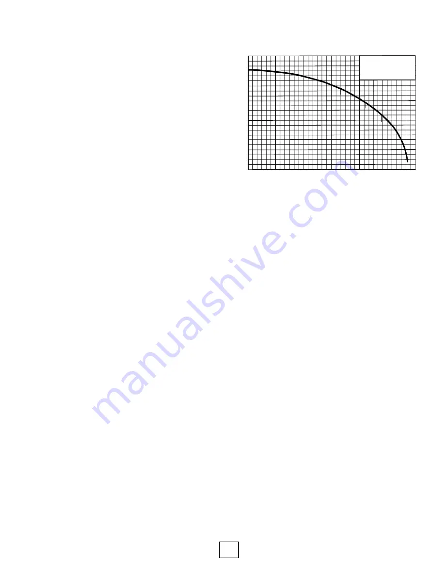
0             10           20            30           40            50           60            70           80            90
                                                              CAPACITY - U.S. GPM

120

110

100

90

80

70

60

50

40

30

20

10

Total H

ead in F

eet

SUCTION LIFT

25’

20’

15’

Meyers QP-15 

1-1/2 HP Self-Priming

Centrifugal Pump

Figure 19: Flush Cart Pump Curve

• 

Turn the 3-way valves on the flow center back 

to the normal operation mode, which closes the 

flush port connections.

• 

Open the ball valves on the flush cart to relieve 

pressure on the hoses. Disconnect the hoses 

from the flow center.

Note: 

Pressurized flow centers and Grundfos UP

series pumps need a minimum of 3psi on the
suction side of the pump to operate. Maximum
operating pressure is 100 psi.

Loop static pressure will fluctuate with the

seasons. Pressures will be higher in the winter
months than during the summer months. In
the cooling mode the heat pump is rejecting

heat, which relaxes the pipe. This fluctuation

is normal and needs to be considered when
charging and pressuring the system initially.

Typical operating pressures of an earth loop are
15 to 50 psi.

Summary of Contents for ACD024B

Page 1: ...Installation Operations Manual BS BT MODELS SPLIT SYSTEM WATER TO AIR HEAT PUMPS REVISION A 20D218 15NN 20D218 13NN...

Page 2: ...tc 17 25 Section 6 Unit Piping Installation Water Quality Flow Center Installation Typical Connections etc 26 37 Section 7 Desuperheater Installation Desuperheater Fitting Kit 38 Section 8 Electrical...

Page 3: ...3 IOM BS BT Models Enertech Global Section 1 Model Nomenclature and AHRI Performance Data Unit Model Nomenclature Decoder Air Handler Model Nomenclature Decoder...

Page 4: ...4 Enertech Global IOM BS BT Models Section 1 Model Nomenclature and AHRI Performance Data Cased A Coil Model Nomenclature Decoder Uncased A Coil Model Nomenclature Decoder...

Page 5: ...TYPE F L COOL F L EER F L HEAT F L COP P L COOL P L EER P L HEAT P L COP BS018 WL TBD TBD TBD TBD TBD TBD TBD TBD GW GL BT024 WL GW GL BT036 WL GW GL BT048 WL GW GL BT060 WL GW GL BT072 WL 65 500 14 3...

Page 6: ...ts are mounted to wooden Pallets for easy handling during shipment and installation Units are protected during shipment with durable cardboard corner posts top and air coil panels Shrink wrap is appli...

Page 7: ...ents 5 Before unit start up read all manuals and become familiar with unit components and operation Thoroughly check the unit before operating Components Master Contactor energizes compressor and opti...

Page 8: ...r area were the ambient temperature will remain above 55 F and should be located in a way that piping and duct work or other permanently installed fixtures do not have to be removed for servicing and...

Page 9: ...gs where ceilings are 8 feet or more at least 50 percent of the return air should be taken back to the heat pump from the ceiling or high sidewall location and not more than 50 percent from the floor...

Page 10: ...Ring 1 Dbl O Ring 1 Dbl O Ring Source Water Conn Comm 1 FPT 1 FPT 1 FPT 1 FPT 1 FPT 1 FPT HWG Water if applicable 3 4 FPT 3 4 FPT 3 4 FPT 3 4 FPT 3 4 FPT 3 4 FPT Refrigerant Charge oz TBD TBD TBD 93 T...

Page 11: ...L PUMP SUPPLY POWER SUPPLY P D E 5174 9 6 4 176 5174 9 6 4 0 Enertech Recommends A Minimum of 2 to 2 1 2 Feet of Service Area Clearance For Installation And Maintenance MODEL SIZE 018 072 CABINET OVER...

Page 12: ...3 4 22 1 4 14 1 4 19 3 4 17 1 4 6 3 4 26 23 16 3 4 14 3 8 4 1 4 4 3 8 4 1 2 MPD072A 6 24 5 8 58 7 8 21 3 4 22 1 4 14 1 4 19 3 4 17 1 4 6 3 4 26 23 16 3 4 14 3 8 4 1 4 4 3 8 4 1 2 Return Air Opening Mo...

Page 13: ...and are 3 4 FPT Center line of drains located from pan corner 1 1 2 for primary and 3 1 2 for secondary 4 Drain pan is injection molded high temperature UL approved plastic 5 All coils are equipped wi...

Page 14: ...208 230 1 152 9 27 1 0 0 0 0 0 0 27 1 33 9 60 01 208 230 1 152 9 27 1 0 0 0 5 0 0 27 6 34 4 60 10 208 230 1 152 9 27 1 0 0 0 0 5 5 32 6 39 4 60 11 208 230 1 152 9 27 1 0 0 0 5 5 5 33 1 39 9 60 20 208...

Page 15: ...2400 2400 2390 1860 1860 1850 930 930 910 C C 1640 1630 1610 1190 1180 1170 610 590 570 D D 1450 1450 1440 1060 1060 1040 550 530 510 A A Norm 2510 2510 2500 2510 2510 2500 1300 1300 1270 B B Norm 250...

Page 16: ...060B 208 230 1 None 0 6 8 1 0 8 5 15 1 10 58 9 70 2 15 32 8 58 9 40 70 2 20 58 9 58 9 70 70 MPD072A 208 230 1 None 0 6 8 1 0 8 5 15 1 10 58 9 70 2 15 32 8 58 9 40 70 2 20 58 9 58 9 70 70 Air Handler E...

Page 17: ...s Table 3 Weights of Refrigerant in Pipes Weight of Refrigerant in Copper Lines Per 10 Feet Liquid Line O D Oz Per 10 Feet Vapor Line O D Oz Per 10Feet 3 8 5 4 5 8 0 7 1 2 10 4 3 4 1 0 5 8 19 5 7 8 1...

Page 18: ...length but not included to figure out vertical liquid lift or vapor rise Table 4 Equivalent Lengths in Feet Equivalent Length in Feet of Straight Pipe For Valves Fittings and Filter Driers Line Size O...

Page 19: ...g Radius Street Ell 45 Ell Notes A crankcase heater and Bi flow liquid line solenoid valve are required if total equivalent length is greater than or equal to 50 feet or the vertical separation is gre...

Page 20: ...evaporator section Vapor line P traps should be installed at the outlet of the air handler and at the bottom of the vapor line drop 75 feet maximum equivalent line length 20 feet maximum vertical sepa...

Page 21: ...ve 70 F the unit should be charged in cooling for the most accurate results If the return air temperature is below 70 F it may be necessary to run the system in emergency heating mode to raise the ind...

Page 22: ...BD 2 80 TBD TBD 2 1 TBD 1 85 TBD TBD 2 1 TBD 1 45 TBD TBD 2 8 TBD 5 50 TBD TBD 2 7 TBD 5 60 TBD TBD 2 5 TBD 5 70 TBD TBD 2 3 TBD 4 75 TBD TBD 2 3 TBD 3 80 TBD TBD 2 2 TBD 2 85 TBD TBD 2 2 TBD 2 45 TBD...

Page 23: ...Source Coax Suction Discharge Compressor Section Liquid Line Temp measured at service valve Liquid Service Valve Heating TXV Air Coil Return Air Cooling TXV Air Handler Thermometer F 1 2 Vapor Service...

Page 24: ...ill not be stable if there is not a liquid lock at the liquid line i e there is some subcooling at the liquid line Record the liquid line pressure and the saturation temperature most gauge sets show s...

Page 25: ...Pressure Measurement Locations Suction Discharge R 410A Manifold Gauge Set Source Coax Suction Discharge Compressor Section Liquid Line Temp measured at air handler Liquid Service Valve Heating TXV Ai...

Page 26: ...rrosion of the internal parts are two of the potential problems The Department of Natural Resources or your local municipality can direct you to the proper testing agency Please see Table 8 for guidel...

Page 27: ...al plumbing codes Part Number Description ACDT1A EZ Trap Kit ACDT2A EZ Trap 1 Kit customer must provide a 1 S x 3 4 Mips adapter Typical Pressurized Flow Center Installation The flow centers are insul...

Page 28: ...Link and GPM Series Flow Centers Section 6 Unit Piping Installation Terminal Box Orientation Equally important to pump longevity is terminal box orientation See Figure 10 for proper control box orient...

Page 29: ...n Pressurized Flow Center Equipment Pad 2 Polythylene Foam Equipment Pad 2 Polythylene Foam Figure 14 External Flush Valves Equipment Pad 2 Polythylene Foam Note P T ports should be angled away from t...

Page 30: ...rts and ball valves Ball valves allow the water to be shut off for service and also help when velocity noise is noticeable through the flow regulator Spreading some of the pressure drop across the bal...

Page 31: ...rom off site Removing Debris During Flushing Most flow center or pump failures are a result of poor water quality or debris Debris entering the loop during fusion and installation can cause noise and...

Page 32: ...way valves to the unit and flush port position Section 6 Unit Piping Installation Turn the pump back on It may be necessary to turn the water supply back on to keep the water level in the reservoir a...

Page 33: ...flush cart ball valves yet Connect the water supply back to the discharge line hose connection and open the ball valve Turn on the water supply and leave it on for 20 to 30 minutes This will stretch...

Page 34: ...compatible with the system materials Stability Will the brine require periodic change out or maintenance Convenience Is the antifreeze available and easy to transport and install Codes Will the brine...

Page 35: ...r Freeze Protection 10 F 12 2 C 15 F 9 4 C 20 F 6 7 C 25 F 3 9 C ProCool Ethanol 25 22 17 12 Methanol 25 21 16 10 Propylene Glycol 38 30 22 15 Geothermal Transfer Fluid GTF Mix according to manufactur...

Page 36: ...low Center Loop Field P T Ports air coil Source Out Source In P T Ports Shut Off Valves Flow Center P T Ports air coil Source Out Source In P T Ports Shut Off Valves Flow Center P T Ports air coil Sou...

Page 37: ...ate Minimum closed loop system flow rate 2 25 to 2 50 gpm ton Bottom flow rate Nominal optimum closed loop system flow rate 3 0 gpm ton Although the rule of thumb is adequate in most areas of North Am...

Page 38: ...e Notes Units that are shipped with a desuperheater do not have the desuperheater pump wires connected to the electrical circuit to prevent accidentally running the pump while dry Pump has to be conne...

Page 39: ...1210004002 7 21P005 01ZZ 8 11210004007 9 11210005007 10 11410001002 11 11410002002 12 11410004002 13 11410005001 14 11410006003 15 11410007001 16 11410008001 17 41P062 01NN 18 11490001002 19 114900000...

Page 40: ...e low pressure switch is open continuously for 30 seconds the compressor operation will be interrupted and the control will go into Section 9 Controls Features Enertech Global geothermal heat pump con...

Page 41: ...ive of a bad sensor The Lockout Board will display the associated fault When diagnosing a possible bad sensor the following table may be used to verify a valid temperature reading Temp F Resistance K...

Page 42: ...temperature DLWT and hot gas compressor discharge line HGT temperature DGT The hot water generator pump is de energized when the leaving water temperature DLWT is above 130 F when the compressor disch...

Page 43: ...AN AUXILLIARY FAULT RELAY LOCKOUT BOARD LED IDENTIFICATION L TERMINAL STATUS LOCKOUT BOARD DIP SWITCHES OFF ON LCT SCT MONITORED FOR FLOW FS TERMINALS IGNORED FS TERMINALS USED TO MONITOR FLOW SWITCH...

Page 44: ...switch TEST must be returned to the OFF position in order to make sure the unit operates with normal sequencing delays While the unit is in Test Mode the status light bottom green will remain off The...

Page 45: ...is energized ten minutes after first stage electric heat W1 is energized Emergency Heat W1 G BS and BT models The fan is started immediately at 2nd stage airflow CFM level based on jumper settings an...

Page 46: ...46 Enertech Global IOM BS BT Models Section 10 Wiring Diagrams 208 230V Single Phase 60Hz Single or Two Stage Commercial...

Page 47: ...47 IOM BS BT Models Enertech Global Section 10 Wiring Diagrams 208 230V Single Phase 60Hz Single or Two Stage DSH Residential Commercial...

Page 48: ...48 Enertech Global IOM BS BT Models Section 10 Wiring Diagrams 208 230V Single Phase 60Hz Single or Two Stage Residential Commercial...

Page 49: ...49 IOM BS BT Models Enertech Global Section 10 Wiring Diagrams 208 230V Three Phase 60Hz Two Stage Commercial...

Page 50: ...50 Enertech Global IOM BS BT Models Section 10 Wiring Diagrams 208 230V Three Phase 60Hz Two Stage DSH Commercial...

Page 51: ...PORT DO NOT USE ANY EXTERNAL SOURCE SIDE INPUT PT PORT Output test readings may be taken at any external PT port 4 Check the geothermal unit s electrical readings listed in the Unit Electrical Data t...

Page 52: ...ource Water Pressure Out Source Water Pressure Drop F F F F F F Heat of Rejection Extraction BTU HR BTU HR F F F F F F Cooling Heating F F F F F F Heating F F F Heating V A GA A Source Water Temp Diff...

Page 53: ...67 2 65 2 62 9 9 0 26 5 36 8 47 1 57 2 67 1 66 6 64 3 61 5 12 0 26 9 37 3 47 8 58 0 66 8 66 1 63 6 60 6 9 0 32 6 45 0 57 4 61 3 87 7 89 7 87 4 83 6 13 5 34 1 46 9 59 7 63 7 87 3 89 2 86 7 82 6 18 0 3...

Page 54: ...D TBD TBD TBD TBD TBD TBD TBD TBD TBD TBD TBD TBD TBD TBD TBD TBD TBD TBD TBD TBD TBD TBD TBD TBD TBD TBD TBD TBD TBD TBD TBD TBD TBD TBD TBD TBD TBD TBD TBD TBD TBD TBD TBD TBD TBD TBD TBD TBD TBD TB...

Page 55: ...lete ECM Temporary Replacement ECM Motor Troubleshooting Troubleshooting a TXV Compressor Troubleshooting Variable Speed Flow Centers Return Conversion for and XT or CT Heat Of Extraction and Rejectio...

Page 56: ...ke off pump and see if there is an obstruction in the pump If pump is defective replace For pressurized systems check loop pressure Repressurize if necessary May require re flushing if there is air in...

Page 57: ...blower and low air flow J WATER DRIPPING FROM UNIT Unit not level Level unit Condensation drain line plugged Unplug condensation line Water sucking off the air coil in cooling mode Too much airflow D...

Page 58: ...apacitor contactor operation See Note A No Yes OK Single Phase 208 230 C Line Winding R Run Winding S Start Winding R efer to the com pressor w on t start flow chart Is the com pressor running N o O K...

Page 59: ...Temp Drop Air Temp Rise F GPM Ton PSIG PSIG F F F F DB 1 5 261 316 71 86 9 10 8 13 7 10 15 26 3 268 323 79 93 9 11 7 12 4 6 16 27 1 5 293 354 101 117 9 12 7 12 11 15 21 33 3 301 362 111 127 9 12 6 13...

Page 60: ...ol Low Low Normal Low Normal High Low High Normal Low Source Water Flow Heat Low Low Normal Low Normal High Low High Normal Cool High High Normal Normal High Normal High Low High Low Load Water Flow H...

Page 61: ..._______________________________________ Date _____________ Model _______________________________________Serial ________________________________________ Antifreeze Type ________________________________...

Page 62: ...ILL NOT PROVIDE THE CORRECT WIRING AND WILL CAUSE THE UNIT NOT TO OPERATE Example 1 WYE STAR Electrical Circuit NOTE Proper Power Supply Evaluation When any compressor bearing unit is connected to a w...

Page 63: ...ER ADDRESS Form submitter Ifdifferent than company OTHER NOTES _______________________________________________________________________________ _________________________________________________________...

Page 64: ...______________________________ PHONE ____________________ ADDRESS __________________________________ CITY _________________STATE PROV ________________ POSTAL CODE _____________ EMAIL OPTIONAL ________...

Page 65: ...65 IOM BS BT Models Enertech Global This page intentionally left blank...

Page 66: ...without notice and may not be as described herein For the most up to date information please visit our website or contact our Customer Service department at info enertechgeo com Statements and other i...

Reviews: