Micropilot M FMR231 with FOUNDATION Fieldbus
Commissioning
Hauser
65
6.6.4
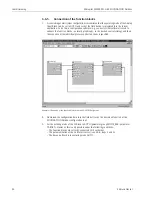
Parametrization of the Analog Input Blocks
Prosonic M has two Analog Input Blocks that can be assigned to the various process variables. The
following descripiton provides an example for the Analog Input Block 1 (Start Index 500).
1.
Enter the desired block name (optional).
Factory setting: ANALOG_INPUT_1_XXXXXXXX
2.
Open the Analog Input Block.
3.
Set the operating mode to OOS (Out of Service) in the parameter group MODE_BLK
(parameter TARGET).
4.
Using the parameter CHANNEL select the process variable that is to be used as the input value
for the function block algorithm (scaling and limit value monitoring). The following settings
are possible:
– CHANNEL = 1: level
– CHANNEL = 2: distance
5.
In the parameter gorup XD_SCALE select the desired engineering unit and the block input
range (measuring range) for the process variable in question (see the example below).
"
Caution!
Make sure that the selected unit is suitable for the measurement variable of the selected
process variable. Otherwies the parameter BLOCK_ERROR will display the error message
"Block Configuration Error" and the block operating mode cannot be set to AUTO.
6.
In the L_TYPE prameter, select the mode of linearization for the input variable (Direct,
Indirect, Indirect Sq Root). For details refer to section 11.7 in the Appendix.
"
Caution!
Note that with the type of linearization "Direct" the configuration of the parameter group
OUT_SCALE must agree with the configuration of the parameter group XD_SCALE.
Otherwise the block operating mode cannot be set to AUTO. Such incorrect configuration is
indicated in the parameter BLOCK_ERROR by the "Block Configuration Error" message.
Example:
• The measuring range of the sensor is 0 to 10 m.
• The output range to the automation system should be 0 to 10 m, too.
The following settings are to be made:
• Analog Input Block 1, Parameter CHANNEL -> "1" (measured level)
• Parameter L_TYPE -> DIRECT
• Parameter group XD_SCALE
XD_SCALE 0% -> 0
XD_SCALE 100% -> 10
XD_SCALE_UNIT -> m
• Parameter group OUT_SCALE
OUT_SCALE 0% -> 0
OUT_SCALE 100% -> 10
OUT_SCALE_UNIT -> m
7.
If required, use the following parameters to define the limit values for alarm and warning
messages:
– HI_HI_LIM -> Limit value for the upper alarm
– HI_LIM -> Limit value for the upper warning
– LO_LIM -> Limit value for the lower warning
– LO_LO_LIM -> Limit value for the lower alarm
The limit values entered must be within the value range specified in the parameter group
OUT_SCALE.
8.
In addition to the limit values you must also specify the action taken if a limit value is exceeded
using the alarm priorities (parameters HI_HI_PRI, HI_PRI, LO_PRI, LO_LO_PRI). Reporting
to the the fieldbus host system only takes place if the alarm priority is higher than 2. For details
refer to section 11.7 in the Appendix.
Summary of Contents for Micropilot M FMR231
Page 95: ...Micropilot M FMR231 with FOUNDATION Fieldbus Technical data Endress Hauser 95 ...
Page 112: ...Micropilot M FMR231 with FOUNDATION Fieldbus Index 112 Endress Hauser ...
Page 113: ......
Page 114: ...www endress com worldwide BA229F 00 ae 06 07 52009950 CCS FM SGML 6 0 ProMoDo 52008600 ...


