Micropilot M FMR231 with FOUNDATION Fieldbus
Technical data
Hauser
87
10
Technical data
10.1
Additional technical data
10.1.1
Input
Measured variable
The measured variable is the distance between a reference point and a reflective surface (i.e.
medium surface).
The level is calculated based on the tank height entered.
The level can be converted into other units (volume, mass) by means of a linearization.
Operating frequency
• FMR231: C-band
Up to 8 Micropilot M transmitters can be installed in the same tank because the transmitter pulses
are statistically coded.
Transmitting power
Average energy density in beam direction:
10.1.2
Output
Output signal
FOUNDATION Fieldbus
Signal Coding
Manchester Bus Powered (MBP); Manchester II
Data transmission rate
31.25 KBit/s, voltage mode
Signal on alarm
• Error symbol, error code and plain text description on the on-site display
• Status byte of the digital signal input
10.1.3
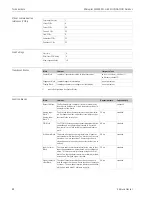
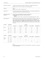
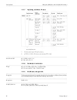
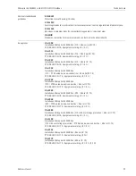
Data of the FOUNDATION Fieldbus interface
Basic Data
Distance
Average energy density
1 m
< 4 nW/cm
2
5 m
< 0,16 nW/cm
2
Device Type
100F (hex)
Device Revision
04 (hex)
DD Revision
01 (hex)
CFF Revision
01 (hex)
ITK Version
4.61
ITK-Certification Driver-No.
IT035500
Link Master (LAS) cabable
yes
Link Master / Basic Device
selectable
yes; Default: Basic Device
Number VCRs
24
Number of Link-Objects in VFD
24
Summary of Contents for Micropilot M FMR231
Page 95: ...Micropilot M FMR231 with FOUNDATION Fieldbus Technical data Endress Hauser 95 ...
Page 112: ...Micropilot M FMR231 with FOUNDATION Fieldbus Index 112 Endress Hauser ...
Page 113: ......
Page 114: ...www endress com worldwide BA229F 00 ae 06 07 52009950 CCS FM SGML 6 0 ProMoDo 52008600 ...


