background image


45 / 81


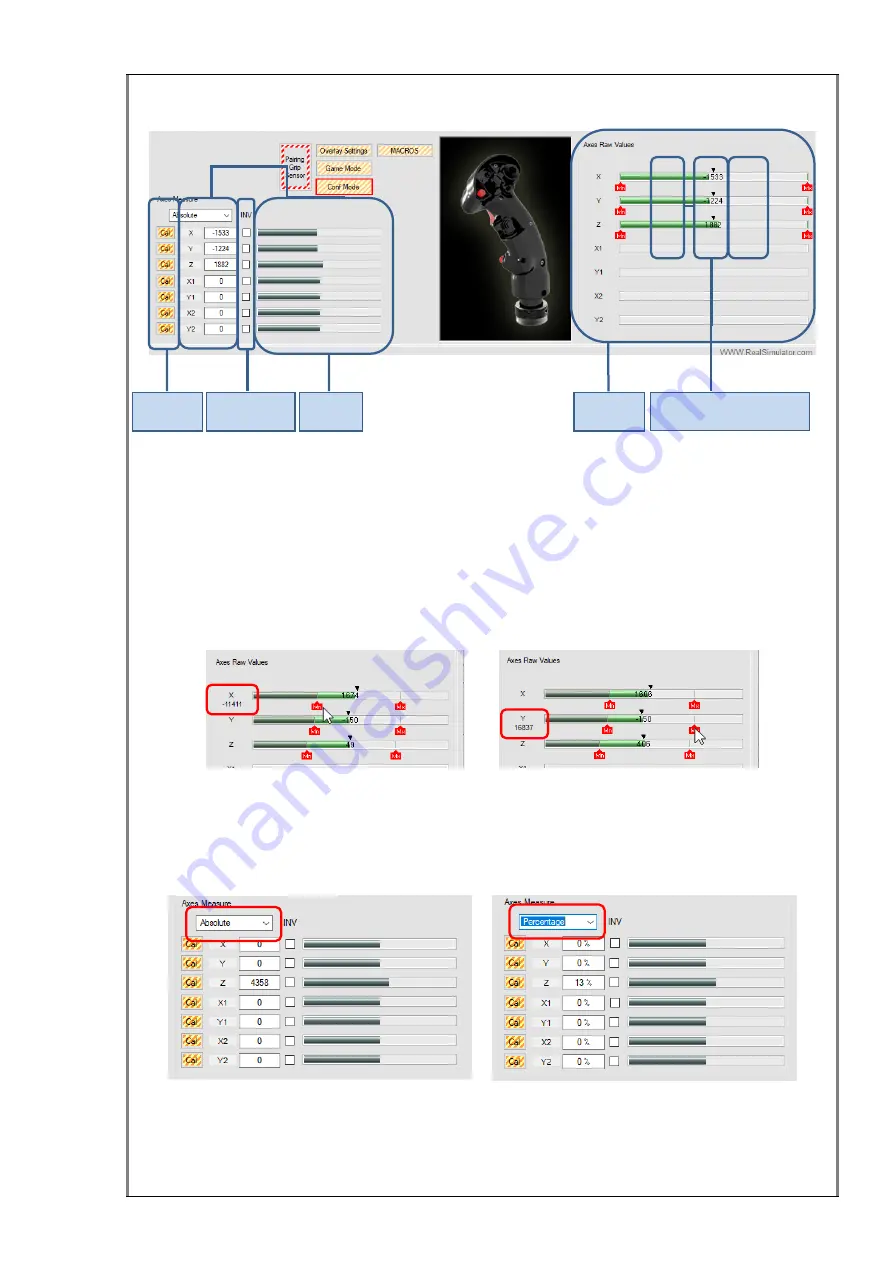
The  image  below  shows  the  different  informative  areas  related  with  the  axes 
calibration. 


Axes  Raw  Values

 group box shows the internal measures of each F18CGRH analog 

axis, numerically and graphically through a green progress bar with the numeric value 
in  the  centre.  Each  axis  has  two  red  icons  to  identify  the  maximum  and  minimum 
positions and a black icon for the centre position. 
  
Values of associated icons (Maximum, Minimum and Centre) can be visualized putting 
the mouse over the icon and modified manually by the user by double-clicking the icon. 
For an explanation about how to do this, please see the section 

Manually  configure 

Raw Axes


X axis Minimum value                                      Y axis Maximum value 

Axes  Measure

  group  box  shows  the  Direct  X  information.  This  information  is  shown 

numerically  in  text  boxes  and  graphically  in  progress  bars.  The  numeric  information 
can be displayed in 

Absolute

 or 

Percentage

 format. To change it, select the preferred 

option in the combo box. 


Absolute format                                                Percentage format 

 
The  axes  calibration  procedure is  very  easy,  and  it is  guided  with instructions  on  the 
screen. However, we are going to show you step by step how to do it.  
 

Calibration 

buttons 

Axes Raw 

measures 

Axes DX 

measures 

Axes Inversion 

Checkboxes 

Minimum, Maximum and 

Centre icons 

Summary of Contents for RealSimulator Home F18CGRH

Page 1: ...ELECTRONICA MECANICA Y CONTROL S A RealSimulator User Guide F18CGRH...

Page 2: ...F18CGRH UserGuidev1 00 EMYCSA RealSimulator Avda Manoteras 22 nave 42 28050 Madrid Spain Phone 34 91 383 83 25 E mail technic realsimulator com...

Page 3: ...hifter and Toggle 65 Digital Mouse 66 Overlay Settings 67 Load Save and Print an xml configuration file 69 Working offline with the F18CGRH 71 Documentation 72 F18CGRH and FSSB R3L 73 Overview 73 Firm...

Page 4: ...Document Revision History Revision Number Date Description 1 00 2020 07 17 First release...

Page 5: ...interferences with other devices or nets in any case home problems not product problems that as you imagine they are very difficult to fix remotely For your peace of mind typically the grips must wor...

Page 6: ...two versions the F18CGRH and a special version named Collector s Edition F18CGRH CE The main differences are the superficial finish the BLE communication module and the analog axes Both are identical...

Page 7: ...en is connected to the R3L base h Firmware upgradeable through BLE so you could need a 4 0 or higher BLE dongle if your PC doesn t have BLE included The F18CGRH is manufactured in high density resin w...

Page 8: ...ected by Bluetooth BLE no available USB port is necessary The computer only needs a BLE connection integrated in the motherboard or through a dongle The computer must run under Windows 8 1 or higher b...

Page 9: ...four modes native ON basic COMP center removed OFF and double click DClick Test window called Output 56 DX buttons can be enabled or disabled for every slot 56 keystrokes can be enabled or disabled f...

Page 10: ...IMPORTANT Communication for configuration upgrading and full device information is made by BLE1 so you will need a computer running Windows 8 1 or 10 preferably and a BLE connection If your computer...

Page 11: ...e control with 4 levels 1 1 3 4 1 2 1 4 Sensitivity control for Roll Pitch and Yaw 0 100 Roll Control Assistance ON OFF BFA Pitch and Roll level Off Min Med High Full Precision mode ON OFF Keystrokes...

Page 12: ...real jet and as a side stick It is shipped as a center stick but if it is going to be used as a side stick you can easily turn its position for a more ergonomic pilot usage For that you only need to u...

Page 13: ...align the two connectors to avoid damaging the pins or connectors For that purpose both connectors have visible marks as you can see in the picture above Powering from a stick base The F18CGRH grip c...

Page 14: ...e In addition some operating system requirements need to be met because Windows 7 and 8 0 do not support BLE devices In these OS versions the F18CGRH is not fully operational it is just a standard sti...

Page 15: ...to a powered base and the left status led is blinking If it is not blinking unplug and plug the power or press the SENSOR CONTROL TMS center RECCE DMS center buttons simultaneously on the stick to res...

Page 16: ...t A new window for installation will open showing an installation progress bar and it will be closed automatically when the device is installed Now the device is displayed in the Device and Printers w...

Page 17: ...e needs to be performed only once when you receive the device or also after a remove action for upgrade for example It will be connected automatically every time you turn on the computer We made a vid...

Page 18: ...duct User Guide To download the tools please go to the Downloads page of the RealSimulator website by clicking the hyperlink below https realsimulator com downloads and download the latest version of...

Page 19: ...r but the procedure will be identical with any new version In any case you should have the following window where setup_RS_Tools_V1_03 exe is the tools installer To install it please run the file by d...

Page 20: ...Guide select the Complete setup type and click Next to continue Or select Custom if you want to choose the features to install and click Next to continue The wizard is now ready to start the installat...

Page 21: ...lete Wait until the wizard finishes the installation and click Finish The installation is now finished and the applications are ready to be used In addition after the installation you will find two ne...

Page 22: ...he DCC and RS_HID_DEV_TOOL applications the RealSimulator devices User Guide and the FSSB R3 BluePrint The applications are installed in the following folders C Program Files x86 RealSimulator Code DC...

Page 23: ...already installed the RS_TOOLS or not In any case there is not more devices with similar name to create a confusion To better understand the next explanation you must imagine the F18CGRH as a device...

Page 24: ...firmware update procedure is valid only for computers running Windows 8 1 or 10 preferably and a BLE connection As we explained above it is absolutely necessary to have the F18CGRH connected through t...

Page 25: ...ons pressed simultaneously is not usual so it is very very difficult to accidentally launch this sequence but if you launch it the only way to exit of this status is to update the device Afterwards th...

Page 26: ...ng an installation progress bar and it will be closed automatically when the device is installed You can find the new device installed in the Device and Printers window Now you can start the DCC appli...

Page 27: ...l only be in normal colour when the device starts the update First the Select the firmware to update message will blink in red so click the Load button to open the Open Firmware File window to select...

Page 28: ...module automatically and will activate the new firmware Now to complete the procedure it is necessary to remove the device F18CGRH Bootloader and to add the main device RS F18 CGR HOME following the p...

Page 29: ...29 81 website https realsimulator com videos f16 or directly by clicking the image or hyperlink below F16SGRH Upgrading...

Page 30: ...fferent options offered by the device to get the maximum performance from your hardware Since the pairing and calibration process is done through the exchange of parameters between the RS_HID_DEV_TOOL...

Page 31: ...cking the RS_HID_DEV_TOOL desktop icon or click the Windows START button and select All Apps Realsimulator RS_HID_DEV_TOOL If the User Account Control window appears click YES to continue Select the F...

Page 32: ...V To change the information shown in the white textboxes you have to click the numeric Up Down control associated the values will change between the max and min values assigned to that setting 3 Pairi...

Page 33: ...on the assigned DX button turns on and the keystroke is shown in the Output box This area contains a textbox for the slot names buttons to SWAP COPY PASTE and CLEAR the slot information and two button...

Page 34: ...d more information in the section Overlay Settings to show or hear the name of the active slot it is necessary to change the mode to the Game mode so changes of slots with the rotary switch will updat...

Page 35: ...ion chapter NOTE 2 The application can be used in offline mode without the F18CGRH connected to configure the slots save the information and recover it later when the F18CGRH is attached You can see m...

Page 36: ...slot for refueling another for NAV another for A G etc You can have up to 8 different situations This is equivalent to having 8 different joysticks each one fit for a different situation and the chang...

Page 37: ...rotary and press the Save button Please pay attention and understand the previous explanation it is very important to configure the F18CGRH b Memory area this area contains the slots information that...

Page 38: ...n to pass the information from Instant area to the slot memory in Memory area At this moment the system will display an alert button to inform you that the memory area has different information than t...

Page 39: ...the settings and reconfigure the system operation This way the status LEDs show the active slot number in binary and the active configuration is loaded in the Instant area When you are configuring th...

Page 40: ...ing and allowing thereby the new pairing to have information about the magnetic fields of the game room and compensate the irregularities it will allow a better YAW precision As you will need to move...

Page 41: ...20 25 numbers of Counter Let s see step by step how the pairing is done 1 After clicking on the Pairing Grip Sensor button a new informative window appears to instruct you to start rotating the YAW a...

Page 42: ...p in the Roll axis To continue click the OK button 6 Now rotate the grip 360 degrees or more over the Roll axis until the Counter reaches the number 199 7 At that moment a new informative window appea...

Page 43: ...ly to the bars movements and keep in mind that when a value reaches the maximum the next value is the minimum and vice versa 12 If the movements suit you accept the pairing by clicking in the alert bu...

Page 44: ...image or hyperlink below F16SGRH Pairing Axes calibration overview As we mentioned at the end of pairing procedure after the pairing it is necessary to calibrate each analog axis The calibration allo...

Page 45: ...ouble clicking the icon For an explanation about how to do this please see the section Manually configure Raw Axes X axis Minimum value Y axis Maximum value Axes Measure group box shows the Direct X i...

Page 46: ...xis in the Axis Measure group box A new small window will appear with instructions for the axis calibration Following the instructions move the stick to the left and right to achieve the minimum and m...

Page 47: ...positions To start the calibration click the Cal button associated to the axis in the Axis Measure group box A new small window appears with instructions for the axis calibration Following the instru...

Page 48: ...ss bars the Maximum Minimum and Center positions To see a parameter value you must hover the mouse pointer over the parameter icon and the measure will be displayed for 4 seconds under the raw axis na...

Page 49: ...50 Clicking with the mouse in the test box you can write the new value 9000 To finish the operation click on the OK button to accept the written value If the value is correct the window closes and the...

Page 50: ...d explanation Digital Mouse DX events and Keystrokes generation by pulses Additional slot change thanks to the Shifter and Toggle functions Adjustable LEDs lighting level SWled function We will explai...

Page 51: ...be always 0 when that slot is active Pay attention because this setting is also applied to the Full Scale Control For example if you set the FSC to 2 4 and the sensitivity to 50 with these two setting...

Page 52: ...and the selection is done with the Up Down indicator associated We suggest selecting almost the Med option for a center value stable PRECISION MODE This feature allows the user to reduce the sensitiv...

Page 53: ...to control the views In TRIM mode the hat switch information is sent as four independent switches in DX buttons 27 28 28 and 30 to be used as TRIM which is its function in real life NOTE in both mode...

Page 54: ...er 4 DX buttons generated by the combination of press first center and after the up down right or left position So each hat has 9 DX buttons associated The DX Button Centre feature allows selecting th...

Page 55: ...s plus the 5 way TRIM hat switch positions No valid DX buttons are shown in grey boxes In DCLICK mode all center positions are enabled but they are available by double button press In the image below...

Page 56: ...off on off on on off off off on In OFF mode the status LEDs show the slot number in binary mode as we mentioned in the How the F18CGRH works section In ON mode the status LEDs show also in binary mod...

Page 57: ...ctions of User Guide remember to save in both parts regularly To the right of the Slot Name text box you can find the Explanation Keystrokes and Names buttons The first one allows changing the keystro...

Page 58: ...ton the standard buttons CANCEL to cancel the action CLEAR to clear the text box content OK to accept and validate the key codes sequence two buttons LWin and RWin to manually enter theses key codes i...

Page 59: ...ck the keystroke text box where you entered the key codes and write the comment you want The explanation info is not necessary it is only a help to remember the keystroke action Finally you can check...

Page 60: ...PASTE allows doing the standard actions of copy and paste with the slot data To copy a slot to another select with the rotary switch the source slot and click on the COPY button then select the destin...

Page 61: ...map of the game or a USA keyboard layout printed and you can press on your keyboard the key of the game key map although it is different Here you have a link to download and print the USA keyboard la...

Page 62: ...be composed by none one or a combination of these 8 keys LWin RWin LShft RShft LCtrl RCtrl LAlt and AltGr Also the key code text box can store a PAUSE this allows you to configure standby times withou...

Page 63: ...text box to enter the PAUSE and set the delay time to 20 With the macro configuration finished it is time to test it For this you can directly close the window because the system saves the configurat...

Page 64: ...he user while the button is pressed It allows to automatically send pulses instead of an ON signal while the button is pressed As a result of this feature the DX button state will be pulsed and if you...

Page 65: ...ndard button in another slot As you see in the previous images we have configured the Direct X button 0 of slot number 1 to send up to a maximum of two pulses of 0 01s with a spacing of 0 04s if the b...

Page 66: ...slot We can select as launcher button between None if you don t want to use the feature Trigger1 WR Pinky not operative in this grip Paddle not operative in this grip NWS and Trigger2 The Shifter Tog...

Page 67: ...hange the mode to Game before clicking the Overlay Setting button so everything will work properly and we won t need to return to the main window to change the mode After clicking on the Overlay Setti...

Page 68: ...e changed with the numeric up down selector associated Display Overlay this check box enables disables the overlay image over the program window when the program from the list is working and it is det...

Page 69: ...ations are done Usually you can load configurations saved previously or copied from other users and you will also need to save the configurations when finished or while modifying To do this the applic...

Page 70: ...button or only the active slots with the Actives button Also there are two lines with box numbers where all slots are shown upper line and only the active slots lower line In the upper line the 8 slot...

Page 71: ...configuration can t be loaded or saved in it It is only loaded and saved in the computer in the xml file and as the tab is shared by F 16 and F 18 grips by default the configuration shown is a F 16 W...

Page 72: ...ncludes a direct and quick option to access the User Guide For that click Help in the upper menu bar and select DOC to directly access the AppData folder where the user guide is stored After clicking...

Page 73: ...l firmwares developed for the FSSB R3 are valid to use with the F18CGRH grip but they use it as a standard grip without additional buttons and features RealSimulator has developed a special version fo...

Page 74: ...hting this firmware will allows you to play without connection problems because the FSSB R3L assumes all the stick functions and the Bluetooth connection isn t necessary In fact if you install this fi...

Page 75: ...ON OFF COMP and DClick DX events and Keystrokes generation by pulses Additional slot change thanks to the Shifter and Toggle functions Digital Mouse Trim adjust You can see detailed information about...

Page 76: ...ot find the drivers in anyplace Requirements to use RealSimulator grips I want to install a new version of RS_HID_DEV_TOOL or DCC but I cannot uninstall the older one How to know if the computer has B...

Page 77: ...ection Windows 7 and 8 0 do not support BLE devices so in these OS versions the device is not fully operational Running in these OS the device is a standard stick not configurable or upgradeable Only...

Page 78: ...llow the next steps 1 Drag the mouse to the bottom left corner and right click on the Start menu icon 2 Select Settings and click Devices 3 Click Bluetooth and move the Bluetooth toggle to the On sett...

Page 79: ...hen you press the trigger button the axes measures will be reduced to the percent selected in the value text box For example if you set the button to ON the value is 40 and the axis X has a value of 1...

Page 80: ...is a firmware for the FSSB R3L named MJF_FW_F16 18_4_00_x FSSB_R3 that allows you to work with your F18CGRH without the Bluetooth connection and without losing any functionality such as the keystrokes...

Page 81: ...ttons they are not read in the base In this case you must disconnect the F18CGRH and check the pins of 5 pin mini Din connector because they will be bent due to an incorrect insertion To fix the probl...

Reviews: