3.3.3
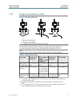
Flange connection on nozzles
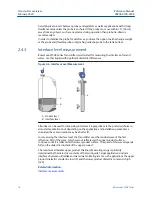
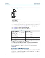
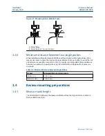
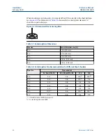
Figure 3-3: Mounting in Nozzles
$
%
&
A. Maximum nozzle height
B. Minimum nozzle diameter
C. Confirm the nozzle does not extend into the tank.
The transmitter can be mounted in nozzles by using an appropriate flange. It is
recommended that the nozzle size is within the dimensions given in
.
Note
The probe must not be in contact with the nozzle (except for the coaxial probe).
Table 3-2: Nozzle Considerations
Description
Flexible single
lead probe
Rigid single lead
probe/
Segmented rigid
single lead
Flexible twin
lead probe
Coaxial probe
Recommended
nozzle diameter
4 in. (100 mm) or
more
4 in. (100 mm) or
more
4 in. (100 mm) or
more
> probe diameter
Minimum nozzle
diameter
1.5 in. (38 mm)
1.5 in. (38 mm)
for probe type 4A
2 in. (50 mm) for
probe type 4B and
4S
2 in. (50 mm)
> probe diameter
Maximum nozzle
height
4 in. (100 mm) +
nozzle diameter
4 in. (100 mm) +
nozzle diameter
4 in. (100 mm) +
nozzle diameter
N/A
(1)
The Trim Near Zone (TNZ) function may be necessary or an Upper Null Zone (UNZ) setup may be
required to mask the nozzle.
(2)
Recommended maximum nozzle height. For coaxial probes there is no limitation on nozzle
height.
(3)
For nozzles taller than 4 in. (100 mm), the long stud version is recommended (option code LS) to
prevent the flexible portion from touching the edge of the nozzle.
Reference Manual
Installation
00809-0100-4308
February 2020
Reference Manual
27
Summary of Contents for Rosemount 3308A
Page 8: ...Contents Reference Manual February 2020 00809 0100 4308 viii Rosemount 3308 Series ...
Page 10: ...Introduction Reference Manual February 2020 00809 0100 4308 10 Rosemount 3308 Series ...
Page 22: ...Transmitter overview Reference Manual February 2020 00809 0100 4308 22 Rosemount 3308 Series ...
Page 74: ...Installation Reference Manual February 2020 00809 0100 4308 74 Rosemount 3308 Series ...
Page 96: ...Configuration Reference Manual February 2020 00809 0100 4308 96 Rosemount 3308 Series ...

