Chapter 3 Installation Testing 11
OK
Comments
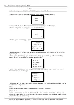
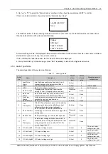
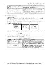
The system model has been set correctly in factory before delivery, check that the setting agrees with
the actual system (NetSure 501 A50: 48V/30A/SET/NONE; NetSure 701 A51 (PS48300-3A/3200):
48V/50A/300/ NONE; NetSure 701 A51 (PS48300-3A/3200-X2): 48V/50A/SET/NONE; NetSure 501
AA0: 48V/30A/300/NONE).
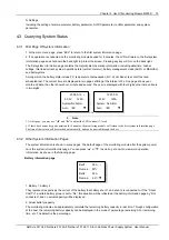
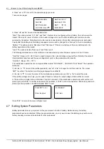
The battery string number set at the monitoring module should be the same as the number actually
connected. (By default: 2)
Set the battery capacity according to the actual capacity of the battery connected to the system.
Default: 300Ah.
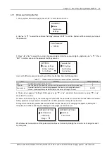
Configure the temperature coefficient according to the battery manufacturer’s requirement. Setting
range: 0-500mV/°C. By default: 72mV/°C. (if no temperature sensor is installed, do not set this
parameter)
Set the charge current limit according to your needs. Setting range: 0.1~0.25C
10
. (By default: 0.1C
10
)
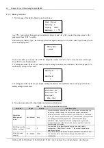
Set the monitoring module according to the voltage suggested by the battery supplier.
Floating Charge (FC) voltage range: 42V ~ Boost Charge (BC) voltage. Default: 53.5V.
BC voltage range: FC voltage ~ 58V. By default: 56.4V.
For batteries that do not need BC, set the BC voltage to FC voltage plus 0.1V.
Put through the battery MCBs and connect the batteries.
3.3 Alarm Check And System Operation Status Check
Alarm check
Check that all functional units can trigger alarms that can be displayed on the monitoring module.
OK
Comments
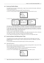
Pull out one rectifier. The “Rect N Com Failure” alarm should be triggered. Insert the rectifier in. The
alarm should disappear. Repeat the same procedures on other rectifiers.
Remove battery MCB 1. The “Batt1 Failure” alarm should be triggered. Put on the MCB. The alarm
should be cleared. Repeat the same on battery MCB 2.
Switch off a load MCB connected to a load route. The alarm “Load N Failure” should be triggered.
Switch on the MCB, and the alarm should be cleared. Repeat the same on the other load MCBs.
Remove all the battery input MCBs. Keep only one rectifier in operation. Through the monitoring
module, adjust the rectifier FC voltage to make it lower than the alarm point. The alarm “DC Voltage
Low” should be triggered.
Keep the rectifiers in operation. Set through the monitoring module the battery management
parameter to “Manual”. Enter the maintenance menu at the monitoring module. Select “Disconnect”
and confirm it. The battery protection contactor should be open, and the “BLVD” alarm should be
displayed at the monitoring module.
Note: when the preceding alarms are generated, the monitoring module will give alarms after approximately 3s. Refer to
4.5Querying Alarms And Setting Alarm Plans
6.5Querying And Handling Alarms
querying alarms.
System operation status check
There should be no alarms during normal system operation. The system operation status check can be conducted
through the monitoring module.
For the parameter query method, refer to
using M800D. Refer to
6.3 Querying System Status
and
6.4 Querying Rectifier Status
if using M501D.
OK
Comments
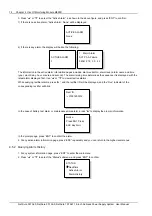
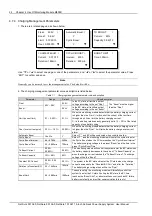
The system model is NetSure 501 A50: 48V/30A/SET/NONE; NetSure 701 A51 (PS48300-3A/3200):
48V/50A/300/ NONE; NetSure 701 A51 (PS48300-3A/3200-X2): 48V/50A/SET/NONE; NetSure 501
AA0: 48V/30A/300/NONE
The monitoring module should display the correct AC voltage.
The monitoring module should be able to display the DC voltage. The difference between the
displayed voltage and that measured at the bus bar should be less than 1%.
The monitoring module should display the battery current. The difference between the displayed and
measured battery current should be less than 1%.
Check the number of the rectifier through the monitoring module. The number should be consistent
with the actual number.
NetSure 501 A50, NetSure 501 AA0, NetSure 701 A51 19-Inch Subrack Power Supply System User Manual

